.png)
Push-Pull Inverter 12V to 220V
Project Overview: Building a 12V to 220V Push-Pull Inverter
In this project, we design and construct a 12V to 220V push-pull inverter. This circuit is specifically designed to convert 12V DC into 220V DC, making it suitable for powering devices with AC input that internally use a bridge rectifier, such as power supplies, phone chargers, laptop chargers, TVs, and computers. However, it is not suitable for inductive devices like fans or transformer-based power supplies without additional modifications.
To power all AC appliances, this circuit must be used in conjunction with a full-bridge inverter stage that converts 220V DC to 220V AC. Below, we outline the steps to build the inverter, including calculations, components, and considerations.
.jpg)


Key Components and Requirements
-
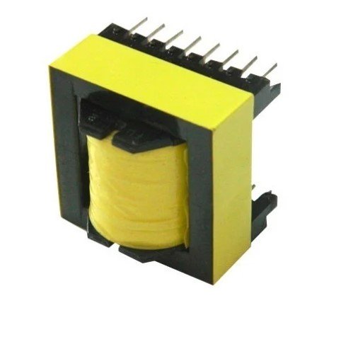
Ferrite Core Transformer:
- Acts as the main step-up component for converting 12V to 220V DC.
- You can purchase one or recycle from old devices such as ATX power supplies.
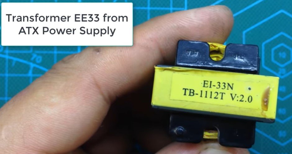
To recycle ferrite trasformer watch:
To buy watch:
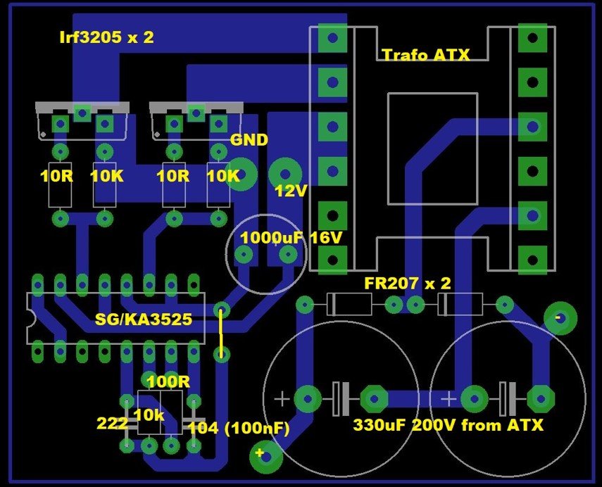
Circuit:
-
Driver IC:
- SG3525: Used for generating the high-frequency PWM signal to drive the MOSFETs.
-
MOSFETs:
- Power transistors for the push-pull configuration, switching the 12V input through the transformer.
-
Capacitors:
- Input and output capacitors to filter and smooth the voltage.
-
Fast Recovery Diodes:
- FR207: Used for rectification after the transformer.
Transformer Design and Calculations
Transformer Type:
Ferrite core transformer (e.g., EE15).
Specifications:
- Input Voltage (Vin): 12V DC
- Output Voltage (Vout): 220V DC
- Frequency (f): 50 kHz
Steps to Calculate Windings:
-
Core Cross-Section Area (Ae):
- Measure or obtain the cross-sectional area of the core from the datasheet.
- For EE15, assume Ae=1.5 cm2=0.00015 m2A_e = 1.5 \, \text{cm}^2 = 0.00015 \, \text{m}^2Ae=1.5cm2=0.00015m2.
-
Turns Per Volt (TPV):
TPV=1044.44×f×Bmax×Ae\text{TPV} = \frac{10^4}{4.44 \times f \times B_{\text{max}} \times A_e}TPV=4.44×f×Bmax×Ae104Where:
- BmaxB_{\text{max}}Bmax: Maximum magnetic flux density (e.g., 0.2T for ferrite core).
- fff: Operating frequency (50 kHz).
Substituting values:
TPV=1044.44×50×103×0.2×0.00015\text{TPV} = \frac{10^4}{4.44 \times 50 \times 10^3 \times 0.2 \times 0.00015}TPV=4.44×50×103×0.2×0.00015104 TPV≈15 turns/volt\text{TPV} \approx 15 \, \text{turns/volt}TPV≈15turns/volt -
Primary Winding:
- Input voltage: 12V.
- Turns: Np=12×15=180 turnsN_p = 12 \times 15 = 180 \, \text{turns}Np=12×15=180turns.
-
Secondary Winding:
- Output voltage: 220V.
- Turns: Ns=220×15=3300 turnsN_s = 220 \times 15 = 3300 \, \text{turns}Ns=220×15=3300turns.
-
Wire Selection:
- Choose wire gauge based on the current requirements. Use thicker wire for the primary winding since it carries higher current.
Circuit Design
Push-Pull Inverter Circuit:
-
Transformer Connections:
- The primary winding is split into two equal halves, each driven by a MOSFET in the push-pull configuration.
- The center tap is connected to the 12V DC supply.
-
Driver Circuit:
- Use the SG3525 IC to generate a 50 kHz PWM signal.
- Configure SG3525 with appropriate timing components (resistors and capacitors) to set the frequency.
- The outputs from SG3525 are fed to the MOSFET gates via gate resistors.
-
MOSFET Selection:
- Choose MOSFETs with a low RDS(on)_{\text{DS(on)}}DS(on) and sufficient voltage and current ratings.
-
Output Rectification:
- After the transformer, use FR207 fast recovery diodes to rectify the high-frequency AC voltage.
- Add output capacitors to smooth the rectified voltage.
Final Assembly and Testing
-
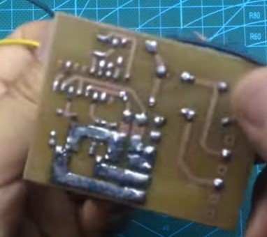
Circuit Assembly:
- Assemble all components on a breadboard or PCB.
- Ensure proper soldering of components and connections to prevent short circuits.
-
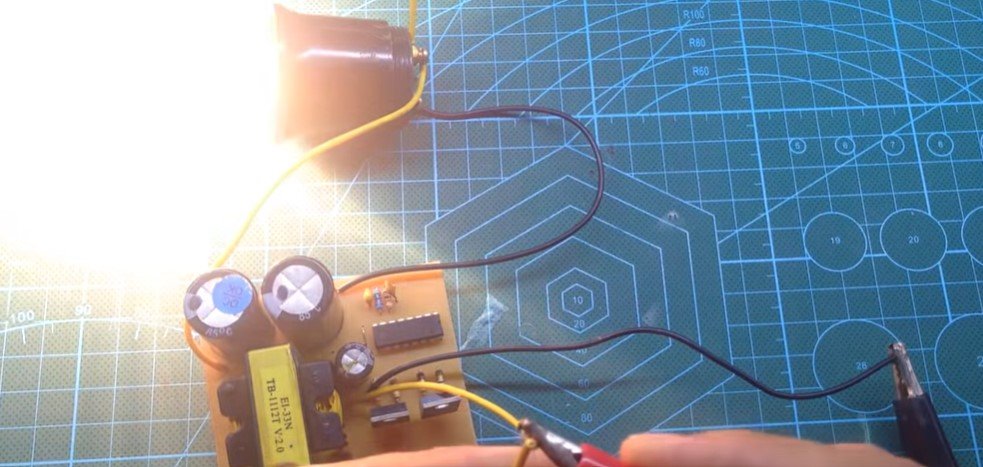
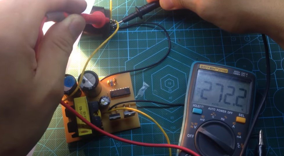
Testing:
- Use a variable power supply to provide 12V DC to the circuit.
- Measure the output voltage using a multimeter. It should be close to 220V DC.
-
Load Testing:
- Connect the output to a suitable resistive load (e.g., a light bulb) to verify performance.
Additional Considerations
-
Heat Dissipation:
- Use heat sinks on the MOSFETs to manage heat generated during operation.
-
Safety:
- Ensure proper insulation and safe handling, as high voltages are present in the circuit.
-
Next Steps:
- To power inductive loads or AC appliances, integrate this circuit with a full-bridge inverter stage to convert 220V DC to 220V AC.
Conclusion
This project demonstrates how to construct a simple and efficient 12V to 220V push-pull inverter. By carefully designing the ferrite core transformer and using appropriate circuit components, this inverter can serve as a foundation for more advanced systems capable of powering a variety of electronic devices.
Posted by Ali Aslan at Friday 10th of January 2025 04:46:42 PM