
High-Voltage H-Bridge Inverter
Project Overview: High-Voltage H-Bridge Inverter (Full-Bridge Inverter)
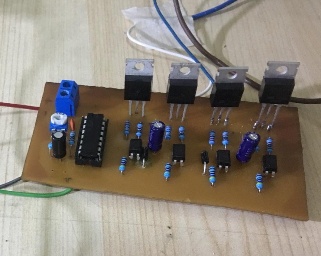
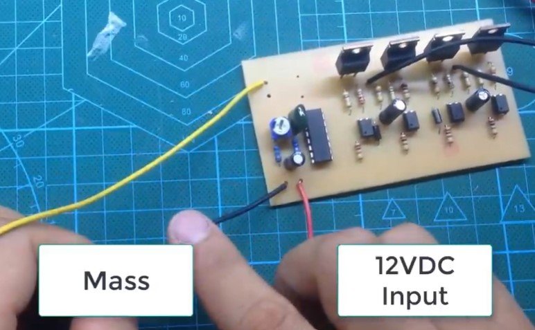
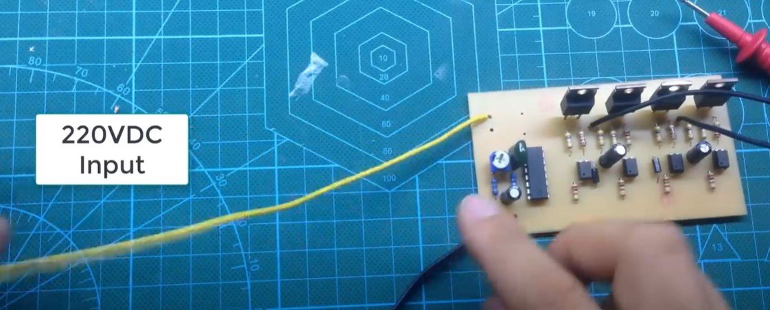
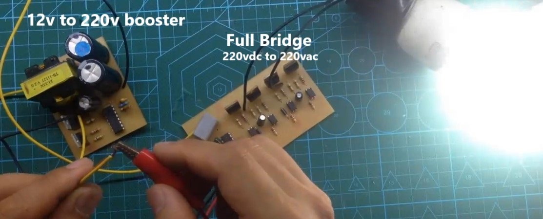
In this project, we have designed and built a high-voltage H-bridge inverter, also known as a full-bridge inverter. This type of circuit is crucial in power electronics, as it efficiently converts high DC voltage into high AC voltage with a modified sine wave output. The input to our circuit is powered by a 220V DC source, which is typically supplied by a booster circuit or a battery pack. The H-bridge configuration processes this DC voltage and converts it into a high-voltage AC output, suitable for powering various appliances and devices.
This circuit is commonly used as the second stage in most inverter designs, where the primary function is to transform high DC voltage into AC voltage.
How the Full-Bridge Inverter Works
The operation of a full-bridge inverter is based on the controlled switching of four power electronic devices (such as MOSFETs or IGBTs) arranged in an H-bridge configuration. Here's a step-by-step explanation of how it functions:
-
H-Bridge Structure:
- The H-bridge consists of four switches (denoted as S1, S2, S3, and S4), connected in a specific configuration.
- The DC input is applied across the bridge, with the positive terminal connected to the upper switches and the negative terminal to the lower switches.
- The AC output is taken from the midpoints of the bridge arms.

-
Switching Operation:
- The switches are controlled in pairs to ensure the DC voltage is alternately applied to the load in opposite polarities. This creates an alternating waveform at the output.
- Half Cycle 1: During the first half-cycle, switches S1 and S4 are turned on while S2 and S3 remain off. This connects the positive terminal of the DC input to one side of the load and the negative terminal to the other, creating a positive voltage across the load.
- Half Cycle 2: In the second half-cycle, switches S2 and S3 are turned on while S1 and S4 are off. This reverses the polarity, connecting the negative terminal to one side of the load and the positive terminal to the other, resulting in a negative voltage across the load.
-
Modified Sine Wave Output:
- To produce a modified sine wave, the switching sequence is controlled using a microcontroller or a PWM (Pulse Width Modulation) circuit. The switches are turned on and off in a specific timing pattern to approximate a sine wave with flat-topped segments.
- This modified sine wave is suitable for many applications where pure sine wave output is not strictly necessary.
-
Key Advantages:
- The H-bridge inverter provides efficient conversion of DC to AC with minimal power loss.
- It allows control over the output frequency and amplitude, which can be adjusted based on the application.
-
Applications:
- Full-bridge inverters are widely used in renewable energy systems, such as solar inverters, where DC voltage from solar panels is converted into AC for household or industrial use.
- They are also utilized in uninterruptible power supplies (UPS), motor drives, and various other AC-powered systems.
-
Protections and Enhancements:
- Snubber Circuits: Protect the switches from voltage spikes caused by inductive loads.
- Dead Time: A brief delay between the switching of complementary pairs to prevent short-circuits across the DC supply.
- Filters: Inductive or capacitive filters can be added at the output to smooth the waveform and reduce harmonics, improving the quality of the AC output.
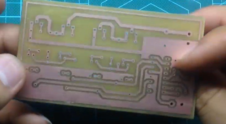
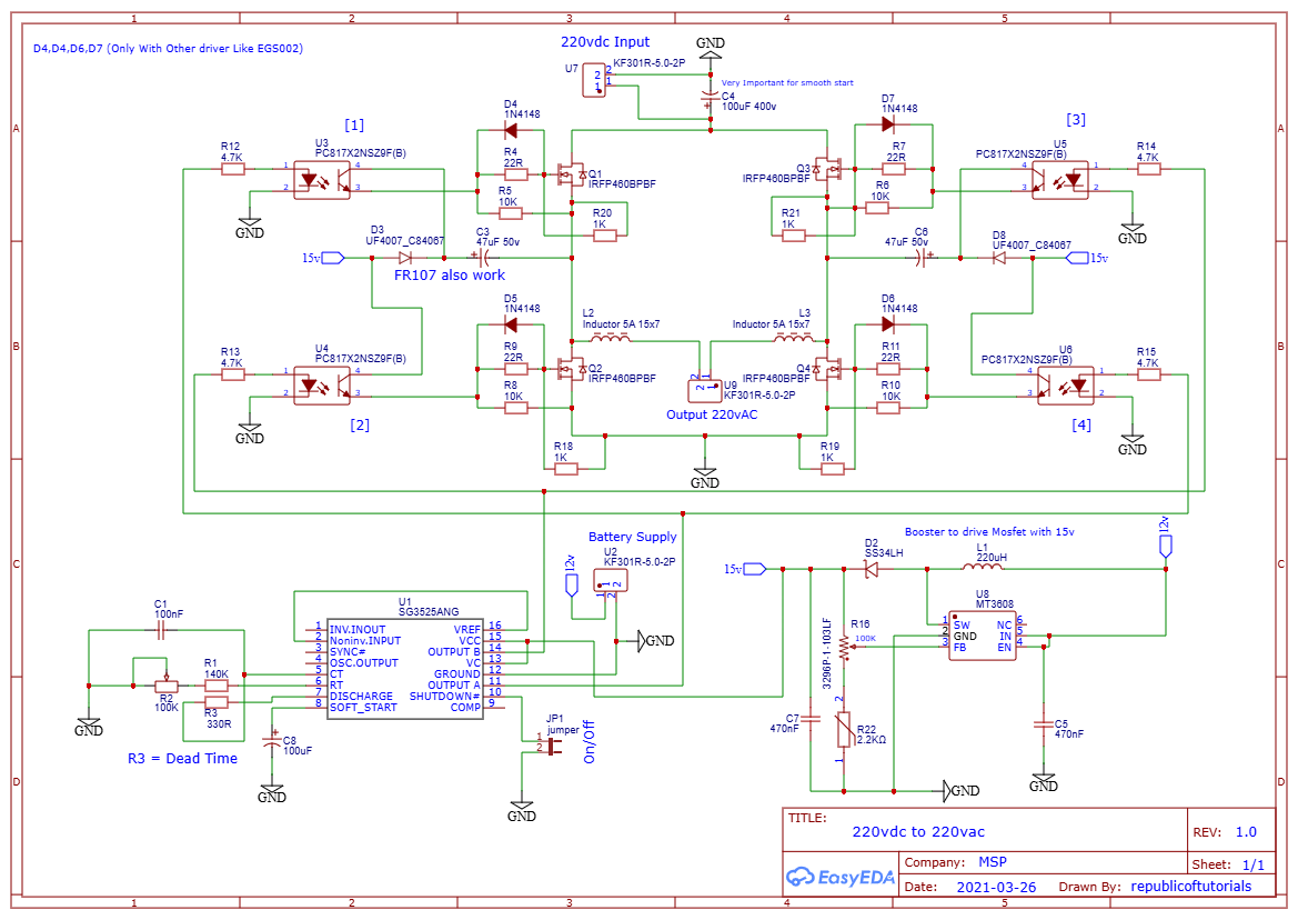
- Circuit Diagram
Summary
The full-bridge inverter is a versatile and essential circuit in power electronics. By alternately switching the polarity of the DC input across the load, it efficiently generates an AC output. With appropriate control techniques, the H-bridge can deliver a modified sine wave or even a pure sine wave for sensitive applications. This design forms the backbone of modern inverters, ensuring reliable and efficient power conversion in countless systems.
Posted by Ali Aslan at Friday 10th of January 2025 10:22:55 AM