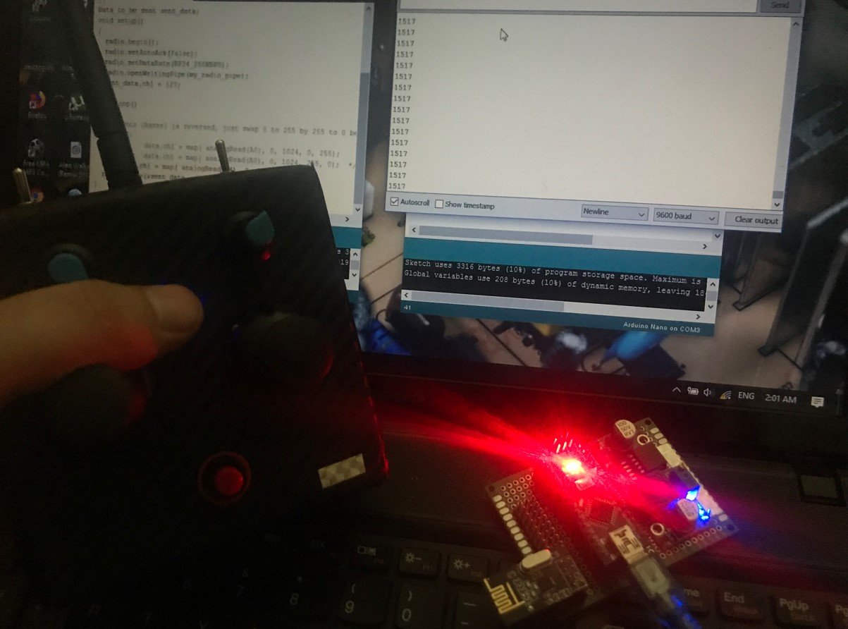
Radio Controller & Receiver
SKY Radio Controller & Receiver
In this project we are making radio controller & receiver and make it work just as a commercial controller.
So, this project will have many parts, a transmitter and a receiver with outputs for each channel. I haven’t tested the range of this one, but with my past projects, which is more than the same, I had good signal up to 1000 meters.

Project Part list: in this project we used these items
Transmitter: Arduino, NRF24, Antenna, Toggle Switches, Potensiometer, Joy Stick, Switch, Led, 2000mah Li-ion battery, 1S 1A charge controller, Buck Converter, Boost Converter, Project box, carbon fiber film and PCB.
Receiver: Arduino, NRF24, Pin Headers, PCB and Buck Converter.
PART 1
Testing NRF24 connection
Before we build our radio controller, first let's test the radio connection between two NRF24 modules. On a breadboard connect the transmitter and the Arduino with only one potentiometer connected to analog pin A0. Use this example schematic for that. Make sure that the SPI connections it’s as in the schematic. You could also wind ground around the MOSI and MISO wires for less noise.
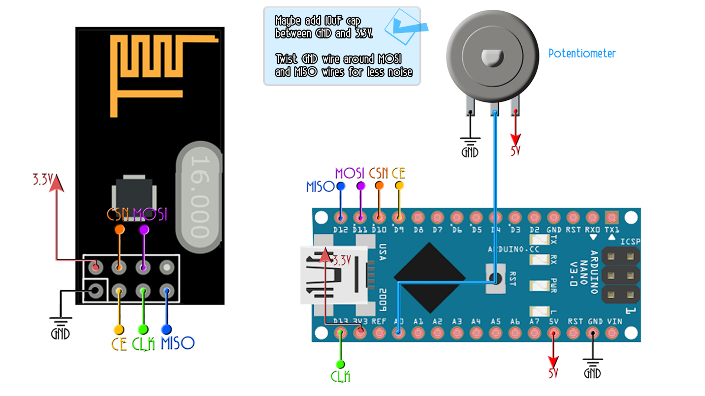
TEST - Receiver
So this above will be the transmitter schematic that will send the data from the potentiometer. Now we do the same for the receiver but without the potentiometer. To print the received data we will use the serial monitor of the Arduino with a baud rate of 9600. Now mount the next schematic for the receiver.
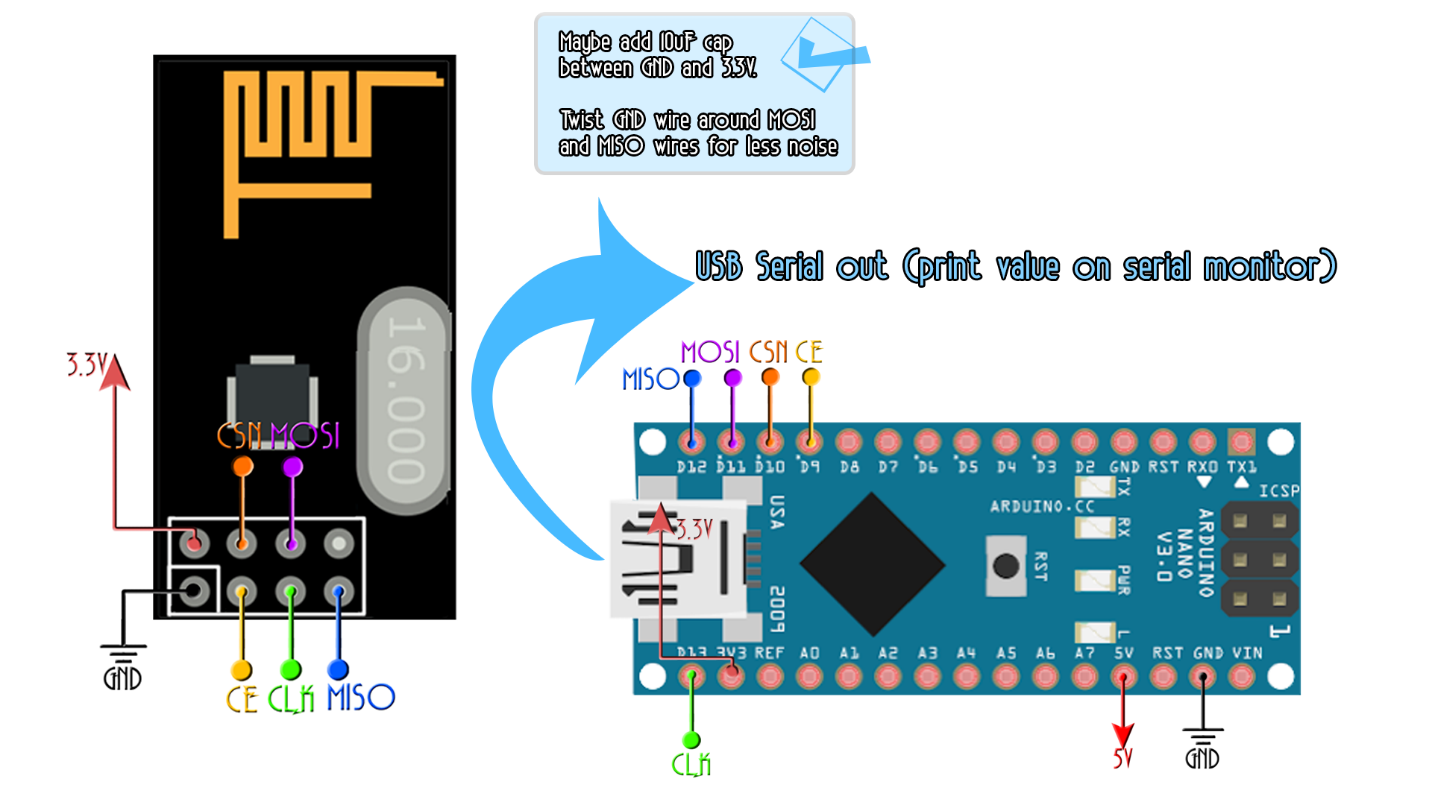
Ok, so now we have the transmitter with a Potentiometer connected to A0 on one breadboard and the receiver on the other. Let's upload some test code and see if we receive the data from the transmitter and print it on the serial monitor.
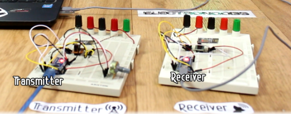
Transmitter code 1 channel
* Transmitter code for the Arduino Radio control with PWM output
GND -> GND
VCC -> 3.3V
CE -> D9
CSN -> D10
CLK -> D13
MOSI -> D11
MISO -> D12
This code transmits 1 channels with data from pins A0 POTENTIOMETER
|
#include #include #include const uint64_t my_radio_pipe = 0xE8E8F0F0E1LL; //Remember that this code should be the same for the receiver RF24 radio(9, 10); // The size of this struct should not exceed 32 bytes struct Data_to_be_sent { byte ch1; }; Data_to_be_sent sent_data; void setup() { radio.begin(); radio.setAutoAck(false); radio.setDataRate(RF24_250KBPS); radio.openWritingPipe(my_radio_pipe); sent_data.ch1 = 127; } void loop() { /*If your channel is reversed, just swap 0 to 255 by 255 to 0 below EXAMPLE: Normal: data.ch1 = map( analogRead(A0), 0, 1024, 0, 255); Reversed: data.ch1 = map( analogRead(A0), 0, 1024, 255, 0); */ sent_data.ch1 = map( analogRead(A0), 0, 1024, 0, 255); radio.write(&sent_data, sizeof(Data_to_be_sent)); }
|
Receiver code 1 channel
Receiver code for the Arduino Radio control with PWM output
GND -> GND
VCC -> 3.3V
CE -> D9
CSN -> D10
CLK -> D13
MOSI -> D11
MISO -> D12
This code receives 1 channels and prints the value on the serial monitor
|
#include #include #include const uint64_t pipeIn = 0xE8E8F0F0E1LL; //Remember that this code is the same as in the transmitter RF24 radio(9, 10); //CSN and CE pins // The sizeof this struct should not exceed 32 bytes struct Received_data { byte ch1; }; int ch1_value = 0; Received_data received_data; void setup() { Serial.begin(9600); //We reset the received values received_data.ch1 = 127; //Once again, begin and radio configuration radio.begin(); radio.setAutoAck(false); radio.setDataRate(RF24_250KBPS); radio.openReadingPipe(1,pipeIn); //We start the radio comunication radio.startListening(); } unsigned long last_Time = 0; //We create the function that will read the data each certain time void receive_the_data() { while ( radio.available() ) { radio.read(&received_data, sizeof(Received_data)); last_Time = millis(); //Here we receive the data } } void loop() { //Receive the radio data receive_the_data(); ch1_value = map(received_data.ch1,0,255,1000,2000); Serial.println(ch1_value); }
|
Ok, so upload the codes above, one to the transmitter and other to receiver. Make sure to open Arduino IDE two times so you could have two COM connected at same time. Go to receiver code and open serial monitor. It should have the value of the potentiometer printed with values from 1000 to 2000. If not, the connection isn't working.
To improve connection, you should do:
-Add 10uF capacitor to 3.3V.
-Wind GND around the SPI pins.
-Solder small copper wire to the PCB radio module

PART 2 - The TRANSMITTER
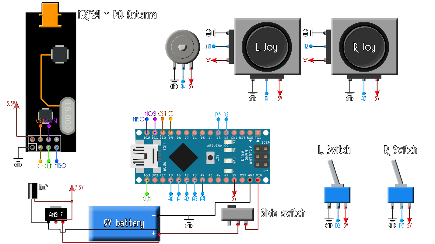
So, let’s start building this project. My transmitter will have 7 channels but it could have more if you want. I will have 4 analog channels for two joysticks. Then I'll use two toggle switches for 2 more digital channels and finally another analog channel for a potentiometer. On a drilled PCB I solder all the components as in the schematic below. For the transmitter you should use a power amplified one so we will have more range. You see, the transmitter needs a powerful radio module, but the receiver should work ok with a normal one as well. If the signal gets to it, it should work just fine.
I take the piece of drilled PCB and I first solder in place the joysticks. They have a thick metal pins, so you will probably have to enlarge 4 holes for each in order to be able to fit it in. Next, I solder the radio transmitter module in the top center position of the board so it won’t have too much interference. Now, a very important step is to solder the Arduino quite close to the radio module. You see, the longer are the wires or PCB connections from the Arduino to the module, the higher the noise will be. So, make sure you have very short connections.
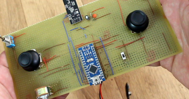
Next, I add the two toggle switches, one on each side and finally the extra potentiometer. To power on and off the board, I’ve added this kind of sliding switch. The battery will be connected to this switch so when we slide it on, the entire board will be supplied.
Finally, I solder the 3.3V voltage regulator with the coupling capacitors and make all the connections between, joysticks, radio module, Arduino and all the components, following the schematic. Now the board is ready. All is there to do is to program it.
NRF24 TRANSMITTER code - 7 channels
* Transmitter code for the Arduino Radio control with PWM output
GND -> GND
VCC -> 3.3V
CE -> D9
CSN -> D10
CLK -> D13
MOSI -> D11
MISO -> D12
This code transmits 7 channels with data from pins A0, A1, A2, A3, D2 and D3
|
#include #include #include
const uint64_t my_radio_pipe = 0xE8E8F0F0E1LL; //Remember that this code should be the same for the receiver
RF24 radio(9, 10); //Set CE and CSN pins
// The sizeof this struct should not exceed 32 bytes struct Data_to_be_sent { byte ch1; byte ch2; byte ch3; byte ch4; byte ch5; byte ch6; byte ch7; };
//Create a variable with the structure above and name it sent_data Data_to_be_sent sent_data;
void setup() { radio.begin(); radio.setAutoAck(false); radio.setDataRate(RF24_250KBPS); radio.openWritingPipe(my_radio_pipe);
//Reset each channel value sent_data.ch1 = 127; sent_data.ch2 = 127; sent_data.ch3 = 127; sent_data.ch4 = 127; sent_data.ch5 = 0; sent_data.ch6 = 0; sent_data.ch7 = 0; } void loop() { /*If your channel is reversed, just swap 0 to 255 by 255 to 0 below EXAMPLE: Normal: data.ch1 = map( analogRead(A0), 0, 1024, 0, 255); Reversed: data.ch1 = map( analogRead(A0), 0, 1024, 255, 0); */
sent_data.ch1 = map( analogRead(A0), 0, 1024, 0, 255); sent_data.ch2 = map( analogRead(A1), 0, 1024, 0, 255); sent_data.ch3 = map( analogRead(A2), 0, 1024, 0, 255); sent_data.ch4 = map( analogRead(A3), 0, 1024, 0, 255); sent_data.ch5 = digitalRead(2); sent_data.ch6 = digitalRead(3); sent_data.ch7 = map( analogRead(A4), 0, 1024, 0, 255);
radio.write(&sent_data, sizeof(Data_to_be_sent)); } |
NRF24 PWM RECEIVER code - 7 channels
* Receiver code for the Arduino Radio control with PWM output
GND -> GND
VCC -> 3.3V
CE -> D9
CSN -> D10
CLK -> D13
MOSI -> D11
MISO -> D12
This code receives 7 channels and create a PWM output for each one on D2, D3, D4, D5, D6, D7and D8
|
#include #include #include #include //To create PWM signals we need this library const uint64_t pipeIn = 0xE8E8F0F0E1LL; //Remember that this code is the same as in the transmitter RF24 radio(9, 10); //CSN and CE pins // The size of this struct should not exceed 32 bytes struct Received_data { byte ch1; byte ch2; byte ch3; byte ch4; byte ch5; byte ch6; byte ch7; };
Received_data received_data;
Servo channel_1; Servo channel_2; Servo channel_3; Servo channel_4; Servo channel_5; Servo channel_6; Servo channel_7; int ch1_value = 0; int ch2_value = 0; int ch3_value = 0; int ch4_value = 0; int ch5_value = 0; int ch6_value = 0; int ch7_value = 0;
void reset_the_Data() { // 'safe' values to use when NO radio input is detected received_data.ch1 = 0; //Throttle (channel 1) to 0 received_data.ch2 = 127; received_data.ch3 = 127; received_data.ch4 = 127; received_data.ch5 = 0; received_data.ch6 = 0; received_data.ch7 = 0; }
void setup() { //Attach the servo signal on pins from D2 to D8 channel_1.attach(2); channel_2.attach(3); channel_3.attach(4); channel_4.attach(5); channel_5.attach(6); channel_6.attach(7); channel_7.attach(8);
//We reset the received values reset_the_Data();
//Once again, begin and radio configuration radio.begin(); radio.setAutoAck(false); radio.setDataRate(RF24_250KBPS); radio.openReadingPipe(1,pipeIn);
//We start the radio communication radio.startListening();
}
unsigned long lastRecvTime = 0;
//We create the function that will read the data each certain time void receive_the_data() { while ( radio.available() ) { radio.read(&received_data, sizeof(Received_data)); lastRecvTime = millis(); //Here we receive the data } }
void loop() { //Receive the radio data receive_the_data();
//////////This small if will reset the data if signal is lost for 1 sec. ///////////////////////////////////////////////////////////////////////// unsigned long now = millis(); if ( now - lastRecvTime > 1000 ) { // signal lost? reset_the_Data(); //Go up and change the initial values if you want depending on //your applications. Put 0 for throttle in case of drones so it won't //fly away }
ch1_value = map(received_data.ch1,0,255,1000,2000); ch2_value = map(received_data.ch2,0,255,1000,2000); ch3_value = map(received_data.ch3,0,255,1000,2000); ch4_value = map(received_data.ch4,0,255,1000,2000); ch5_value = map(received_data.ch5,0,1,1000,2000); ch6_value = map(received_data.ch6,0,1,1000,2000); ch7_value = map(received_data.ch7,0,255,1000,2000); //Creathe the PWM signals channel_1.writeMicroseconds(ch1_value); channel_2.writeMicroseconds(ch2_value); channel_3.writeMicroseconds(ch3_value); channel_4.writeMicroseconds(ch4_value); channel_5.writeMicroseconds(ch5_value); channel_6.writeMicroseconds(ch6_value); channel_7.writeMicroseconds(ch7_value); }
|
PART 3 – Building the Circuit Board (PCB)
So, after we did all testing and written the codes we decide to design pcb or printed circuit board for our project, as you can see we designed a very professional double side pcb and all the connections are designed inside the pcb.

layers : 2 minimum trace width : >=10 mil minimum trace spacing : >=10 mil
minimum drill size : 0.305 mm width : 99.31 mm height : 66.55 mm

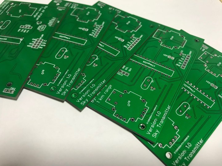
PART 4 – Building the Enclosure
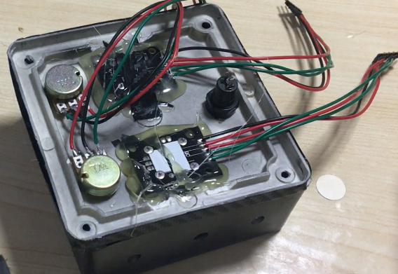
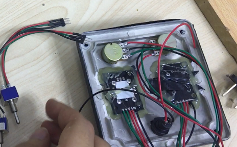
Once we designed the circuit board we decide to design an enclosure box to put everything inside it and make it looks like a real transmitter remote control for doing that we got a project box (10cmX10cmX5cm) we measured size of each part and then we cute holes with the shape of parts, once we did that we paint the project box and did carbon fiber for long lasting, after that we mount all parts such us joy sticks, switches, Pots, charger and antenna
After that we mount the transmitter circuit board and 2000mah li-ion battery inside the box and closed the project box with m4 screws and the transmitter enclosure has been done.

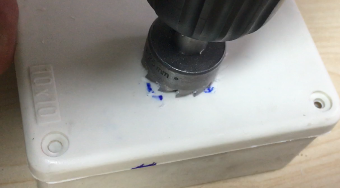
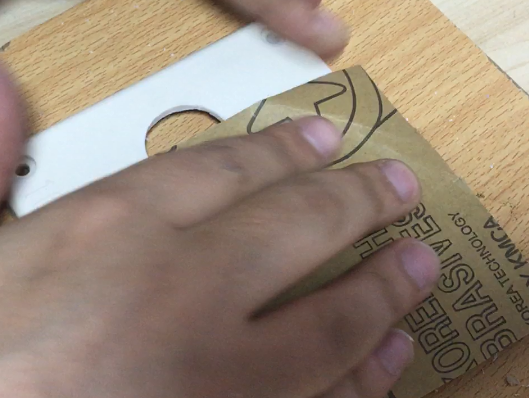
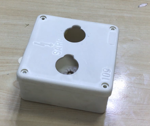


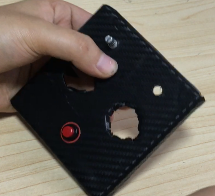
Some photos of building process


PART 5 – The Receiver
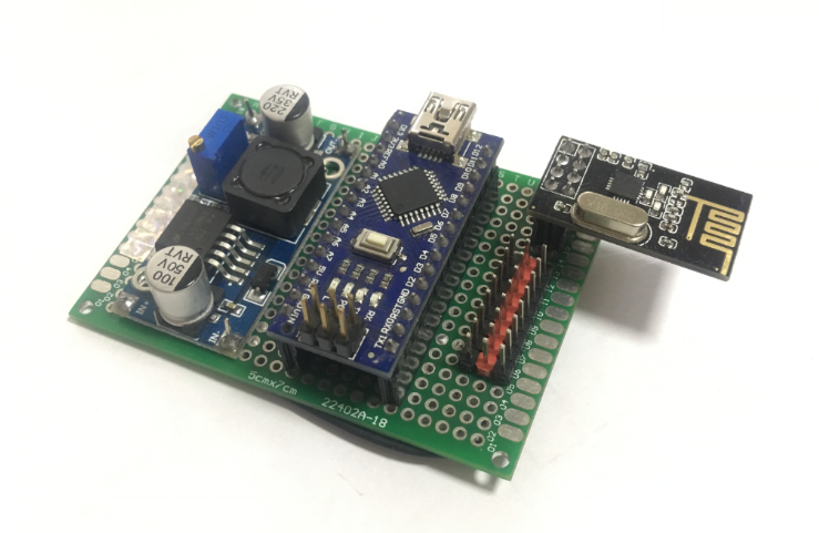
We solder all the receiver parts into a truth hole pcb and placed male connectors for power and signal just like commercial once.
So, we will use the same NRF24 radio module to receive the signal. This module work both as transmitter or receiver and they could also do it both at same, the Data send from the transmitter is received by NRF24 and then it decodes by the Arduino and the microcontroller output a pwm or ppm signal and those signals can be use by any type of pwm speed controllers and devices
Radio control functions and usages
To really get the most out of your new hobby, you need to understand at least the most common radio control functions and features that your new rc system is capable of.
I say 'at least the most common', because most modern rc transmitters are packed with features that you will likely never use!
The absolute fundamental purpose of your rc system is, of course, to control the directional movement of your aircraft, with auxiliary functions being controlled in a secondary manner.
Incidentally, if you don't already know, each controllable function of a radio controlled model is referred to as a 'channel' i.e. a single-channel rc aircraft will have control to just one function, whilst a six-channel aircraft will have six controllable functions.
RC transmitter types
There are essentially two basic categories of radio control systems - surface radios for use with rc cars, boats and other land-based vehicles, and air radios for aircraft.
These days, it's common for a two-channel surface radio to be of the 'pistol grip' design, but two-channel traditional 'stick' transmitters can also be bought and these can be used for simpler rc aircraft, notably gliders.
A multi-channel air radio features two sticks and additional switches, but the big difference between stick transmitters of two or 4+ channels is how the sticks move.
On a 2-channel stick transmitter in use with an rc glider, for example, the right hand stick moves from left to right, with a natural centre i.e. the stick is sprung.
To correspond naturally with the control of the glider, this stick moves the rudder, or perhaps ailerons instead. Either way, this stick controls the left/right directional control of the glider. Moving the stick left will steer the glider to the left, and vice versa.
The left hand stick, also sprung, moves up and down and corresponds naturally with the elevator. In this case, though, up does not mean up; moving the stick upwards (i.e. away from you) will cause the elevator to drop which will result in a dive, whilst moving the stick down (i.e. towards you) will raise the elevator and cause the glider to climb.
The radio control functions of a multi-channel transmitter (shown above, right) become more complicated because each stick moves up and down and left and right. The right hand stick will, for example (*see below), control elevator (up/down) and aileron (left/right) whilst the left hand stick will control throttle (up/down) and rudder (left/right).
Learning to control two actions with one stick may sound complicated but is mastered with practice and will soon become second nature.
*NB: Various modes are used with multi-channel rc systems, determining which sticks operate which controls:
Mode 1: rudder and elevator are controlled by the left stick, throttle and ailerons by the right.
Mode 2: ailerons and elevator are controlled by the right stick, rudder and throttle by the left.
Mode 3: ailerons and elevator are controlled by the left stick, rudder and throttle by the right.
Mode 4: throttle and ailerons are controlled by the left stick, rudder and elevator by the right.
Common radio control functions
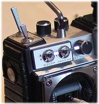
RC channel switches and dials on a txAside from the main stick controls, additional channels are found on toggle switches and/or rotating dials and sliders, all of which can be located on the face or top of the transmitter within easy fingertip reach (the photo shows the top left corner of a transmitter with many extra channels). These extra channels can be utilised to control, for example, flaps and retractable landing gear, and functions such as dual rates will commonly be operated by such switches.
All channels over and above the four primary ones are called auxiliary channels.
The more common radio control functions and features
found on modern rc transmitters include...
RC channels
When talking about channels, there are 2 different meanings in the radio control world; the number of channels an rc system has, as mentioned earlier up the page, and the frequency channel that the system operates on.
Because all radio control systems send out radio signals, just as a traditional radio or TV broadcasting station does, various frequency channels are needed so that more than one rc system can be operated at the same time. So, in most parts of the world, certain channels have been designated, by law, for radio control models and must be adhered to for safety reasons. RC aircraft have their own set of channels while rc surface vehicles have theirs.
For more detailed information on this very important aspect of radio control, see the rc airplane frequencies page.
But with the above in mind, frequency channel control only applies to MHz radio control systems; the newer - and now commonplace - 2.4GHz systems use a different technology, and so frequency channel designation does not apply to them.
A further point to remember when referring to radio frequencies used for models is the modulation. The word modulation refers to the whole process of the radio signal being sent out by the transmitter, received by the receiver and passed on to the servos.
The two standard types of modulation are AM (Amplitude Modulation) and FM (Frequency Modulation), the latter being sub-divided into PPM (Pulse Position Modulation) and PCM (Pulse Code Modulation).
In a nutshell, PCM is the modern digital successor to PPM and does a far better job of guarding against unwanted interference. FM is the most commonly used by nearly all rc aircraft pilots*, while AM is often used on 2 channel surface vehicles and rc toys.
*NB: while the traditional FM MHz rc systems are still in use, the newer 2.4GHz spread spectrum have all but replaced them. Such systems use a completely different frequency band and technology, and it's only a matter of time before the MHz rc systems go the way of the dodo.
Whichever rc system you have, understanding the radio control functions and features on it is very important, to get the most out of it. As with all things in life, it's not necessary to buy the all-singing, all-dancing, most expensive set you can lay your hands on, but do be satisfied that your system will be able to control your aircraft in all the ways that you need.
Summary
The transmitter is based on NRF24 which is low power high frequency transmitter module
The data inputs by switches, joystick and pot into Arduino and it transmit by NRF24 and those data capture and receive by NRF24 receiver module and decode by Arduino and outputs PWM signal to any device which is compatible with PWM.
This Transmitter can also output PPM signal but for now we used PWM output which is more common, This transmitter can transmit up to 1km (1000 meter) and the speed of connection is too fast and that’s why we can use it to control any type of RC device such as Drones (Quadcopter and Hexacopter), UAV, UGV, RC Car and much more.

Posted by Ali Aslan at Sunday 5th of January 2025 05:00:58 PM