
Power Supply 220V to 12V 10A
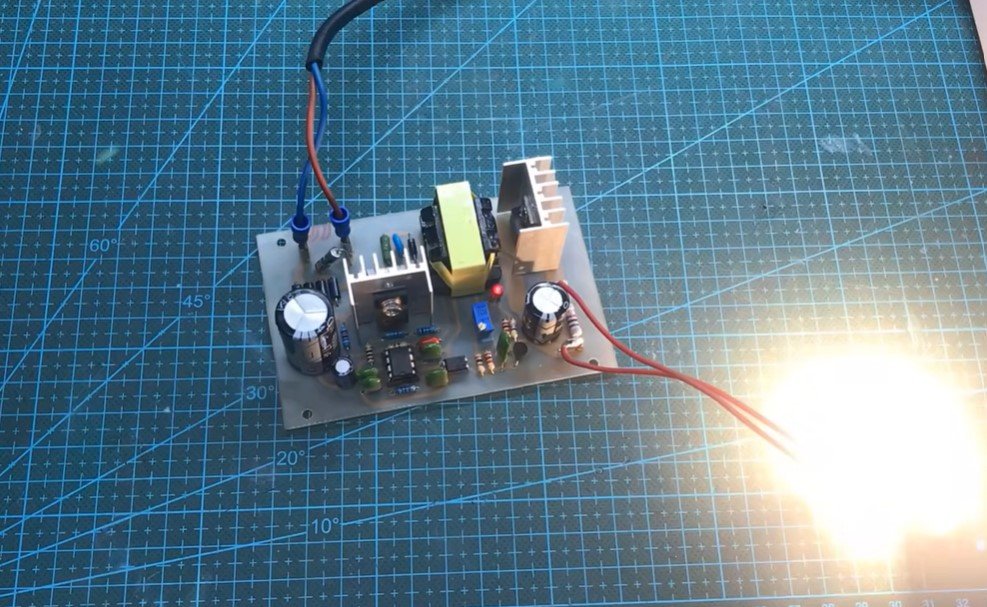
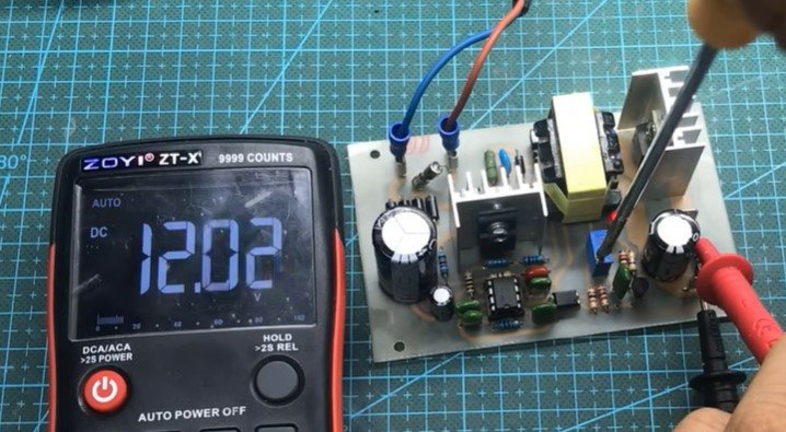
In this project, we design and build a robust power supply that converts 220V AC mains voltage into a regulated 12V DC output with a current capacity of up to 10A. This type of power supply is commonly used for powering DC devices, including electronic gadgets, motors, or even charging 12V batteries.

Key Components and Their Roles
-
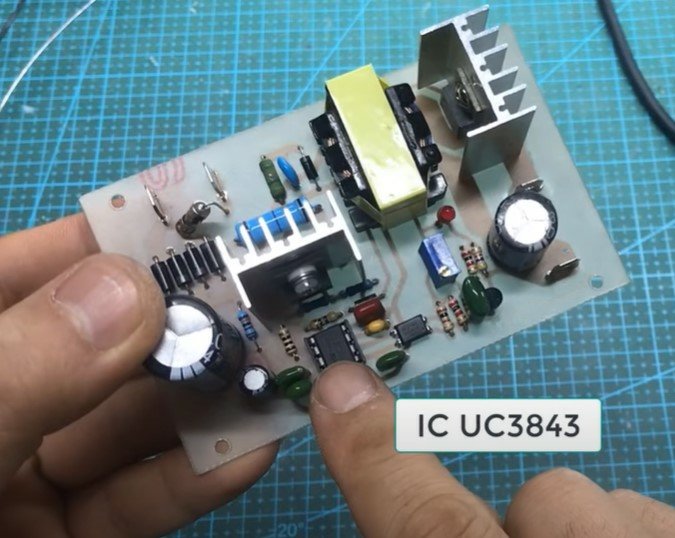
UC3843 PWM Controller IC
At the heart of this project lies the UC3843, a high-performance Pulse Width Modulation (PWM) controller IC. It is widely used in switch-mode power supplies (SMPS) due to its high efficiency and ease of use. The UC3843 operates as follows:- PWM Control: It regulates the output voltage and current by modulating the pulse width sent to the switching device.
- Fast Response: The IC has a high-speed response to load changes, ensuring stability under varying conditions.
- Built-in Protection: It includes features like overcurrent protection, undervoltage lockout, and thermal shutdown for safety and reliability.
- Ease of Integration: The UC3843 requires only a few external components to create a stable and efficient power supply.
-
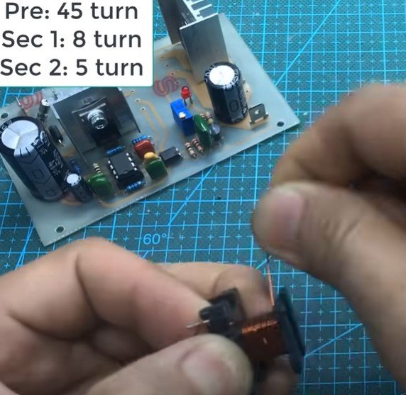
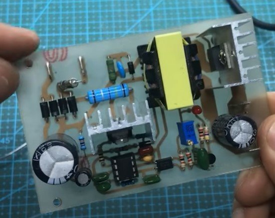
Ferrite Core Transformer
A ferrite core transformer is essential for voltage conversion in SMPS. It works by stepping down the high-frequency AC voltage generated by the PWM controller to the desired DC level. In this project:- Primary Winding: 45 turns
- Secondary Winding 1: 8 turns (responsible for the main 12V output)
- Secondary Winding 2: 5 turns (used for auxiliary purposes, like powering the controller or feedback circuitry)
The high-frequency operation (enabled by the UC3843) allows the transformer to be compact and efficient.
-
Bridge Rectifier and Filter Capacitors
A bridge rectifier converts the incoming 220V AC to DC, which is then smoothed using filter capacitors. This rectified DC serves as the input for the switching section. -
MOSFET or Switching Transistor
A high-speed switching device, such as a MOSFET, operates as a key component to convert the rectified input into a high-frequency signal for the transformer. -
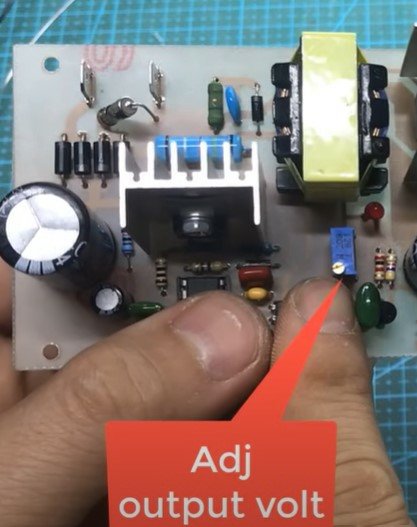
Output Filter and Regulation
The rectified and smoothed output from the transformer is further filtered and regulated to ensure a stable 12V DC output. Capacitors and inductors play a significant role in removing ripples.
Building the Power Supply
-
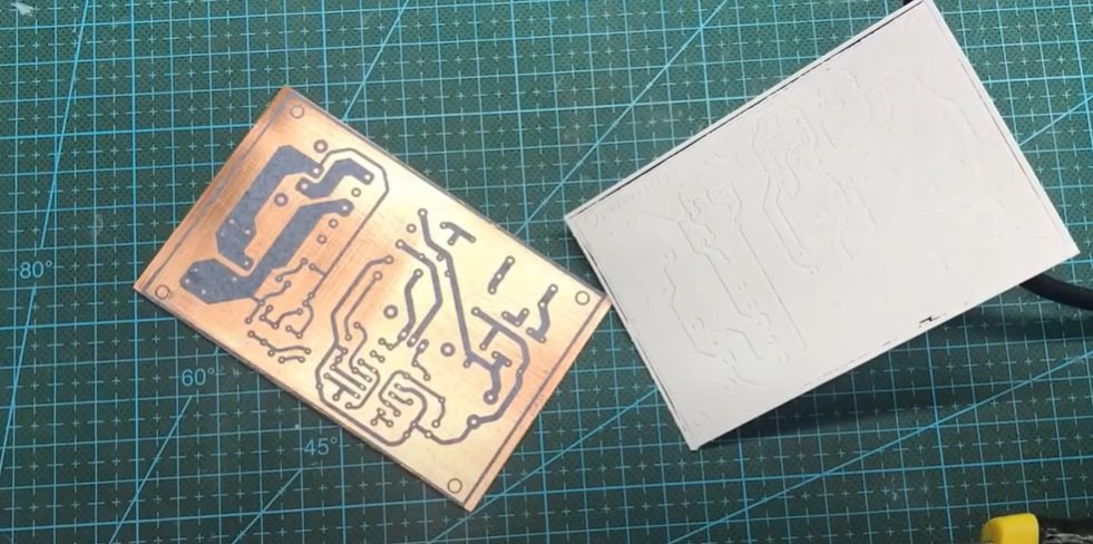
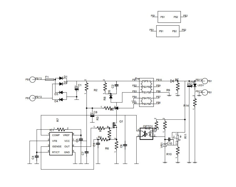
Circuit Design:
Start by designing the schematic, ensuring proper selection of components. The UC3843 circuit should include:- A feedback loop to maintain voltage regulation.
- Proper connections for the PWM output to the gate of the switching transistor.
- Decoupling capacitors for stability.
-
Transformer Winding:
Carefully wind the ferrite core transformer according to the specified turns ratio. Ensure insulation between primary and secondary windings to prevent short circuits.
-
Assembly:
- Mount the components on a PCB.
- Pay attention to layout design to minimize noise and ensure efficient heat dissipation.
-
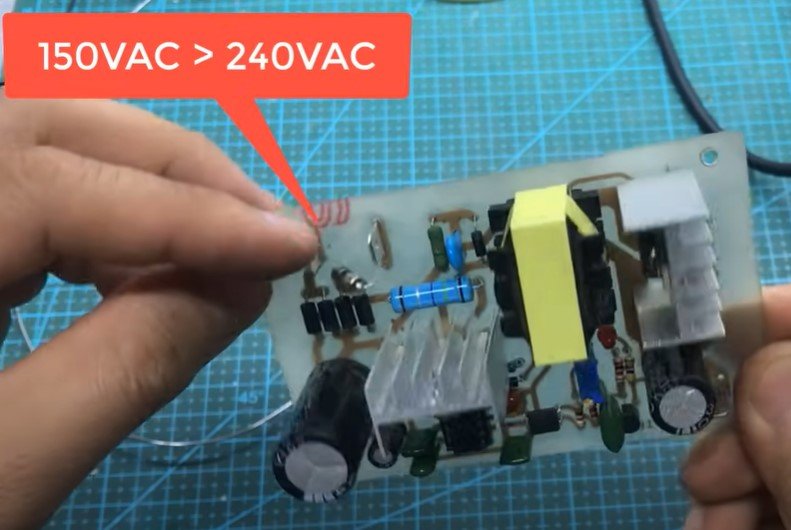
Testing and Debugging:
- Test the circuit using a variac to gradually increase the input voltage.
- Monitor the output voltage and current to confirm stability.
- Use an oscilloscope to check the waveform and ensure proper switching operation.
Applications and Benefits
This power supply is versatile and can be used for:
- Powering high-current DC devices such as motors or LEDs.
- Charging 12V lead-acid or lithium-ion batteries.
- Use in DIY electronics projects.
The project is not only functional but also a great learning opportunity for understanding SMPS design, including PWM control, transformer operation, and high-frequency switching.
Posted by Ali Aslan at Saturday 11th of January 2025 05:58:41 PM