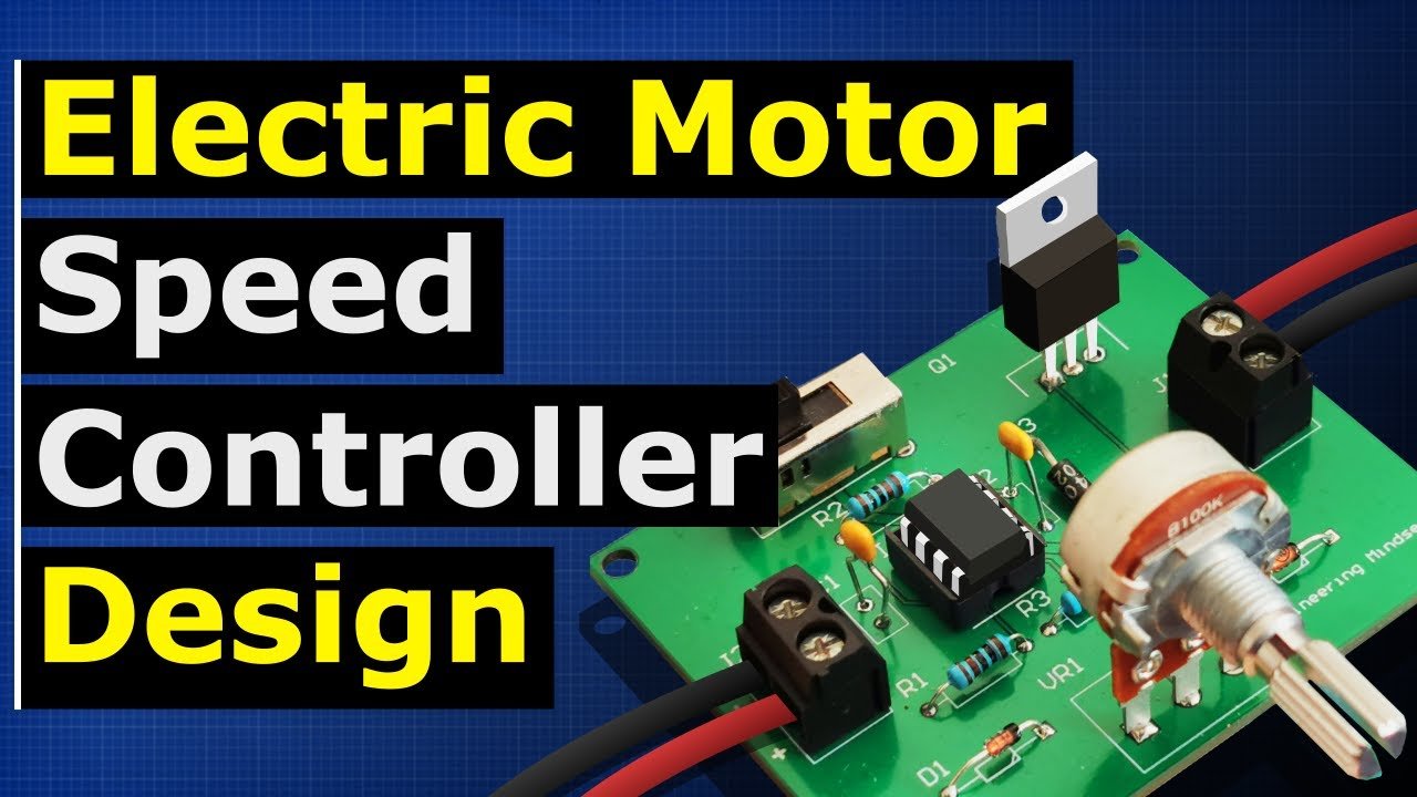
Motor Speed Controller 555 IC
DIY Motor Speed Controller Using PWM and a 555 Timer
Pulse Width Modulation (PWM) is a simple yet effective method used to control the speed of motors in many applications. It operates by varying the "on" and "off" periods of electrical signals, thus controlling the average power supplied to the motor. This article will guide you through creating your very own DIY motor speed controller using PWM and a 555 timer. This circuit can be used to control the speed of practically any motor.
Before we begin, make sure you have the following items:
NE555 timer IC
Variable resistor (potentiometer)
Capacitor (4.7µF and 0.01µF)
Resistors (1kΩ and 10kΩ)
Diode (1N4148)
MOSFET (IRFZ44N)
DC Motor
Breadboard and jumper wires
Power supply
Circuit Design
The 555 timer IC is a versatile device capable of generating accurate time delays or oscillation. In this circuit, we will use it in astable mode to generate a square wave signal, which will form the basis of our PWM signal.
Here's a step-by-step guide to building the circuit:
The 555 Timer IC: Connect pin 8 (VCC) to the positive supply voltage and pin 1 (GND) to ground. Connect pin 4 (reset) to VCC to disable the reset functionality.
Setting up the Astable Multivibrator: Connect a resistor (R1) between pins 7 (discharge) and 8 (VCC). Connect a second resistor (R2) between pins 7 and 6 (threshold). Connect a capacitor (C1) from pin 6 to ground. Connect pin 2 (trigger) to pin 6.
Output and Control Voltage: Connect pin 3 (output) to the gate of your MOSFET. Connect a capacitor (C2) between pin 5 (control voltage) and ground to stabilize the internal voltage levels.
The Motor Control: Connect the drain of your MOSFET to one terminal of your motor. Connect the other terminal of the motor to VCC. Connect the source of the MOSFET to ground. To protect the MOSFET from back EMF, connect a diode across the terminals of the motor, with the anode on the ground side and the cathode on the VCC side.
PWM Adjustment: Connect a potentiometer in place of R2. By adjusting the resistance of the potentiometer, you can adjust the duty cycle of the PWM signal, thereby controlling the speed of the motor.
Working Principle
The 555 timer in astable mode generates a continuous series of pulses, which are then used to drive the MOSFET. The duty cycle of these pulses can be varied by adjusting the resistance of the potentiometer. When the duty cycle is high, the motor receives power for a larger proportion of the time, causing it to spin faster. Conversely, when the duty cycle is low, the motor receives power less often and thus spins slower.
This DIY motor speed controller using PWM and a 555 timer is a cost-effective and versatile way to control the speed of your motors. It's suitable for a wide range of applications, from robotics to home appliances. So get your components together and start building!
Advanced Concepts and Applications
The versatility of the 555 timer and PWM control extends far beyond the basic motor control. You can enhance this project or apply these concepts in other DIY electronics applications. Here are a few ideas:
Bidirectional Motor Control
If you want to control not just the speed but also the direction of a DC motor, you can build an H-bridge circuit. An H-bridge is an arrangement of transistors that allows the voltage across a load to be controlled in both directions. By combining an H-bridge with a PWM speed controller, you can gain full control over a DC motor's speed and direction.
Servo Motor Control
The 555 timer can also be used to generate the PWM signals needed to control servo motors. Servo motors differ from regular DC motors in that they can be positioned at specific angles in addition to being rotated at varying speeds. This makes them ideal for applications like robotics, where precise control over movement is required.
Frequency and Duty Cycle Control
You can modify the 555 timer circuit to have independent control over the frequency and duty cycle. This can be achieved by using two potentiometers: one to control the frequency (by varying the total resistance in the timing circuit) and another to control the duty cycle (by adjusting the ratio of the two resistors in the timing circuit).
Use with Microcontrollers
For even more control over your motor, you could interface this circuit with a microcontroller like an Arduino or a Raspberry Pi. This would allow you to control the motor's speed in response to sensor input, user input, or according to a preprogrammed sequence.
Troubleshooting Tips
If you build the circuit and it doesn't seem to work as expected, here are a few troubleshooting tips:
Check Your Connections: Ensure all components are connected as described in the circuit design. Misplaced wires or components can cause the circuit to malfunction.
Check Your Components: Ensure all components are functioning correctly. You can test resistors with a multimeter, and diodes can be tested for forward and reverse bias.
Check Your Power Supply: Make sure your power supply is providing the correct voltage and current for your motor and the 555 timer.
Adjust the Potentiometer: If the motor isn't responding to changes in the potentiometer, ensure that it's connected correctly and try adjusting it throughout its full range of resistance.
Conclusion
PWM motor control using a 555 timer is a versatile and accessible project for any electronics hobbyist. Not only does it provide a practical introduction to the concept of PWM, but it also serves as a jumping-off point for more advanced projects and applications. Whether you're interested in robotics, automation, or just learning more about electronics, this project has something to offer you.
Posted by Ali Aslan at Wednesday 17th of May 2023 07:27:46 PM

