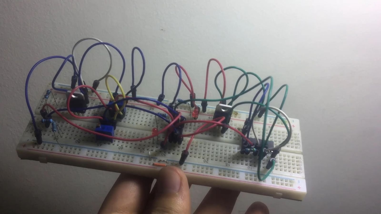
Mechanical Electronic MPPT
How to make MPPT - Mechanical Electronic MPPT
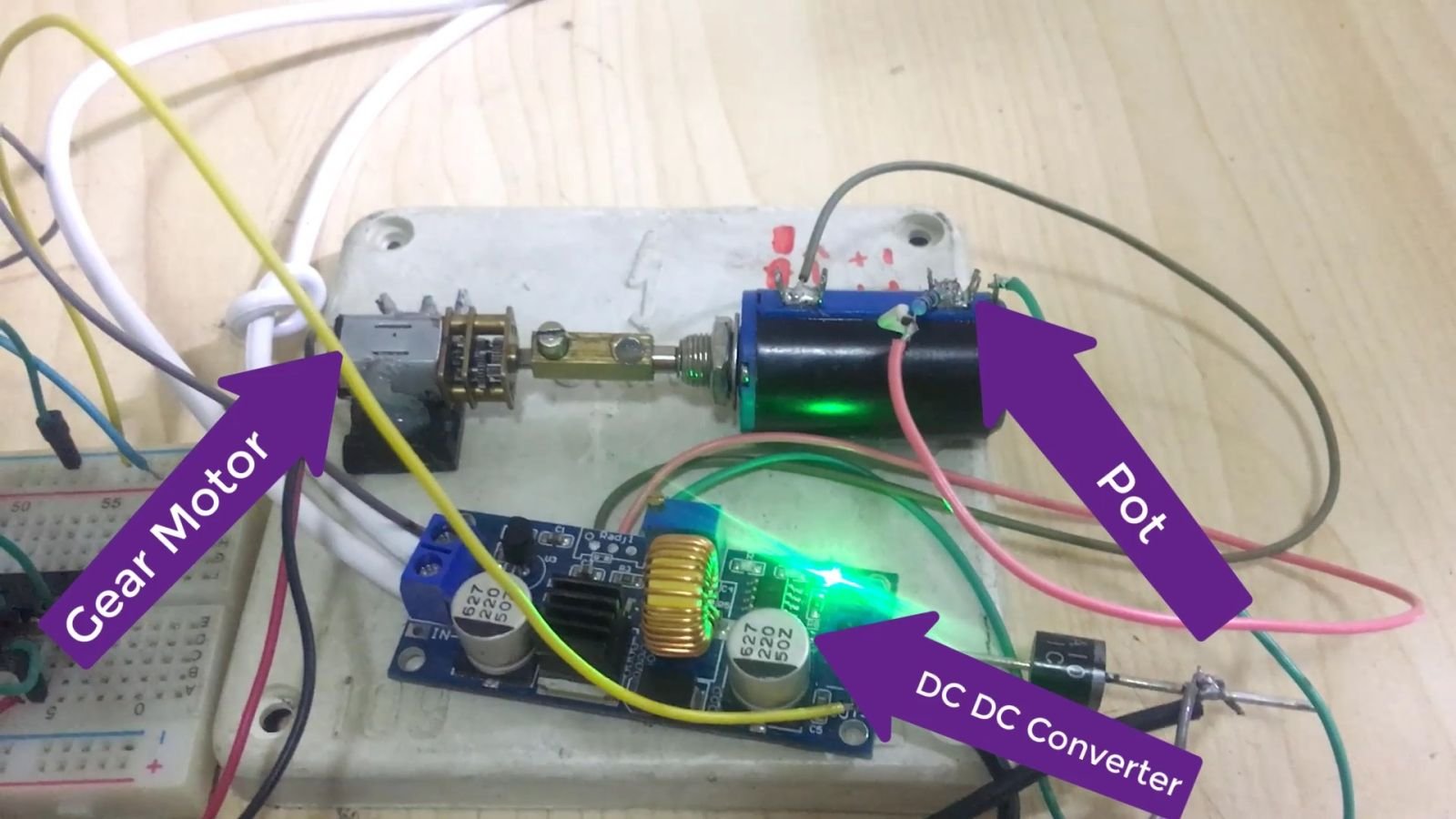
In this project, we used a DC/DC buck converter with feedback pot control, allowing us to adjust the output voltage and current by turning the knob. We then used an op amp circuit with a gear motor to adjust the feedback in response to changes in the solar input.
Constructing a Mechanical Electronic Maximum Power Point Tracker (MPPT) Using a DC-DC Buck Converter
Introduction:
A Maximum Power Point Tracker (MPPT) is a sophisticated technology developed to harness the maximum possible power from Photovoltaic (PV) cells, commonly known as solar panels. The output of PV cells is heavily influenced by environmental factors such as light intensity and temperature. Thus, an MPPT system is essential to dynamically adjust the voltage and current from the PV cells to capture the most power possible.
This project outlines the creation of a Mechanical Electronic MPPT using a DC-DC buck converter, a feedback potentiometer control, an operational amplifier (Op-Amp) circuit, and a gear motor. The novelty of this project lies in the mechanical adjustment of the feedback in response to changes in solar input, enhancing the adaptability of the system.
Components and Materials:
Solar Panel
DC-DC Buck Converter
Feedback Potentiometer
Operational Amplifier (Op-Amp) Circuit
Gear Motor
Power Supply
Assorted cables, resistors, capacitors, and connectors
Conceptual Framework:
The DC-DC buck converter, an integral part of the system, steps down the voltage from the solar panel to a usable level. The feedback potentiometer control is mechanically linked to a gear motor, which adjusts the feedback based on the output of the Op-Amp circuit.
The Op-Amp circuit monitors the solar panel's output voltage and current. Once it detects a variation, it instructs the gear motor to adjust the feedback potentiometer, altering the output of the DC-DC buck converter. This ensures that the PV cells operate at the maximum power point, irrespective of environmental conditions.
Detailed Procedure:
Setting up the DC-DC Buck Converter: Connect the output of the solar panel to the input of the DC-DC buck converter. The output from the buck converter will be connected to the load (the system you are intending to power).
Integrating the Feedback Potentiometer: Connect the feedback potentiometer to the feedback pin of the DC-DC buck converter. Create a mechanical linkage between the feedback potentiometer and the gear motor. This way, the rotation of the motor will adjust the position of the potentiometer, thereby altering the feedback.
Establishing the Op-Amp Circuit: Design the Op-Amp circuit to sense changes in the solar panel's output. The output of this circuit should be connected to an ADC input of the Arduino. This way, the Arduino can process the variations in solar output and respond appropriately.
Connecting the Gear Motor: Connect the control input of the gear motor to a digital output pin on the Arduino. This allows the Arduino to control the rotation of the motor based on the data it receives from the Op-Amp circuit.
Circuit Diagram
Driver op Amp
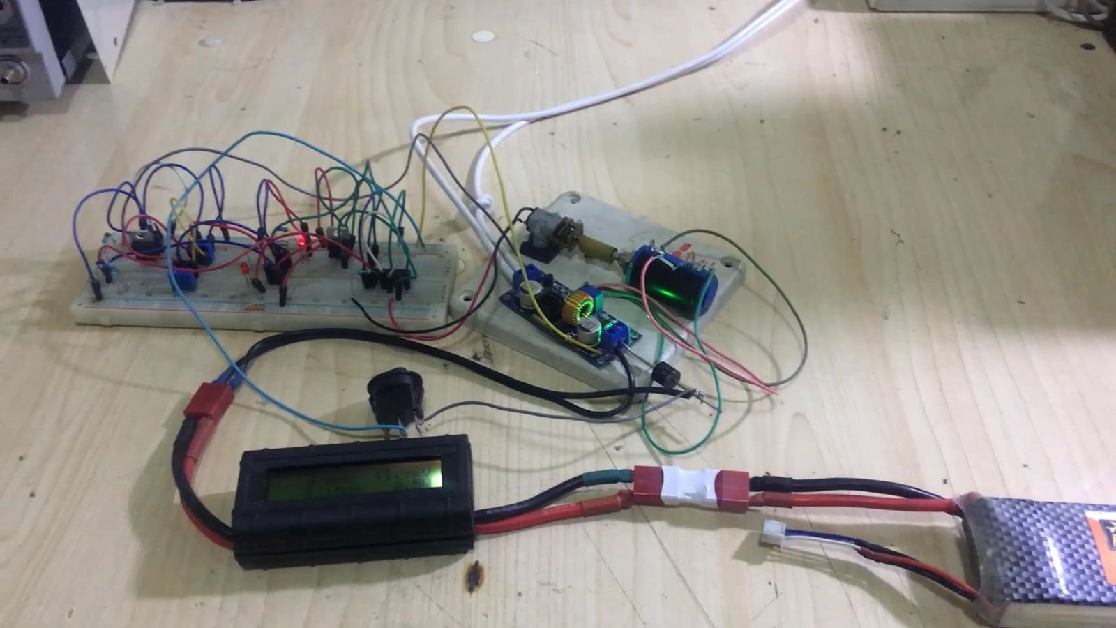
Full Image
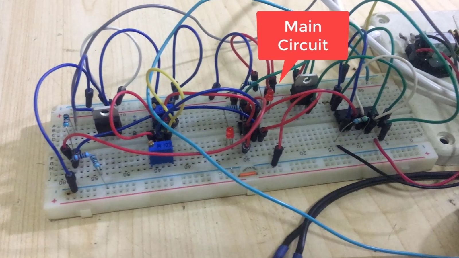
Main Circuit
Testing and Refinement: After setting up the entire system, test it under varying sunlight conditions. If the system's response isn't optimal, adjust the Arduino's programming accordingly. The aim is to ensure that the solar panel always operates at its maximum power point.
Controller
Solar Input and Output
MPPT
MPPT
MPPT MAX
Conclusion:
This project combines mechanical and electronic components to create an innovative MPPT system. Such a system can effectively adapt to environmental changes and ensure that a solar panel operates at its maximum power point at all times. As solar power
Posted by Ali Aslan at Monday 15th of May 2023 04:49:43 AM


