
Inverter Overload Protection
Project Overview: Inverter Overload Protection Circuit
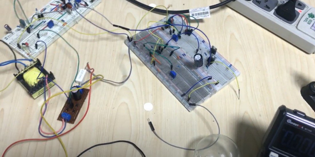
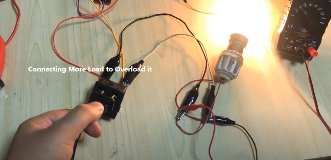
In this project, we designed and implemented an Inverter Overload Protection system. The primary purpose of this circuit is to safeguard the inverter from damage due to excessive load. The system uses a shunt resistor and an operational amplifier (op-amp) circuit to continuously monitor the load current. If the load exceeds a safe threshold, the protection system immediately shuts down the inverter. Once the overload condition is removed, the inverter automatically restarts, ensuring seamless and safe operation.
How the Overload Protection Circuit Works
-
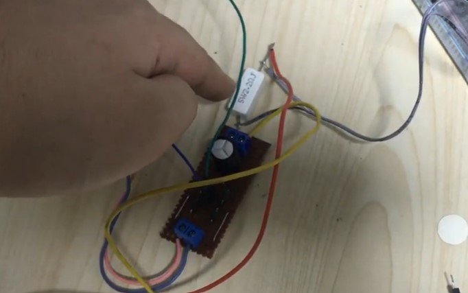
Current Sensing with Shunt Resistor:
- A shunt resistor, a low-resistance, high-wattage component, is placed in series with the inverter output.
- As current flows through the load, a small voltage drop is generated across the shunt resistor according to Ohm’s Law (V=I×RV = I \times RV=I×R).
- This voltage drop is proportional to the load current, making the shunt an effective current sensor.
-
Voltage Comparison with Op-Amp:
- The voltage drop across the shunt resistor is fed to an operational amplifier configured as a comparator.
- A fixed reference voltage is set at one input of the op-amp. This voltage corresponds to the maximum permissible load current.
- The other input of the op-amp receives the voltage drop from the shunt resistor.
-
Overload Detection:
- During normal operation, the voltage drop across the shunt resistor remains below the reference voltage, and the op-amp output stays low.
- When the load exceeds the threshold, the voltage drop across the shunt becomes greater than the reference voltage. This causes the op-amp output to go high, signaling an overload condition.
-
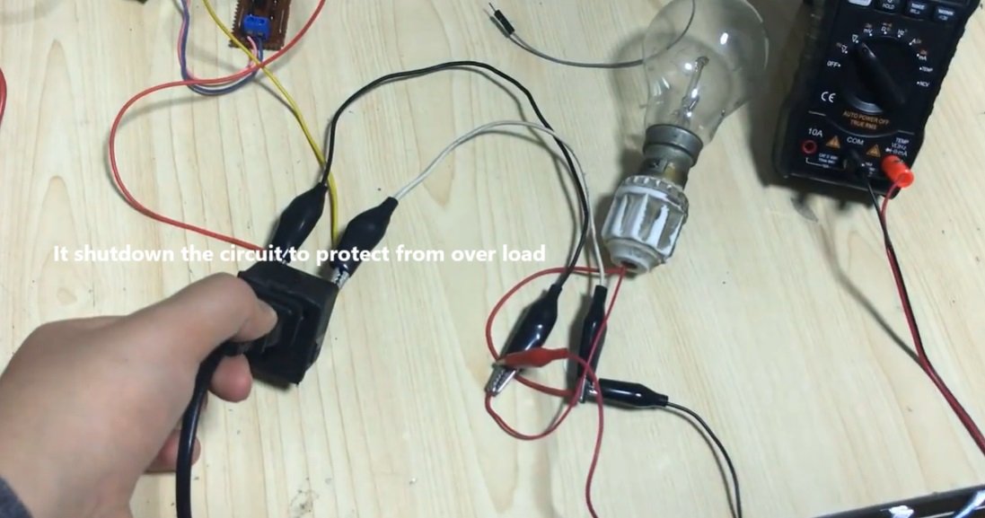
Inverter Shutdown:
- The output of the op-amp is connected to the shutdown pin of the inverter control IC (e.g., SG3525).
- When the op-amp output goes high due to overload, it triggers the shutdown pin, instantly disabling the inverter to prevent damage.
-
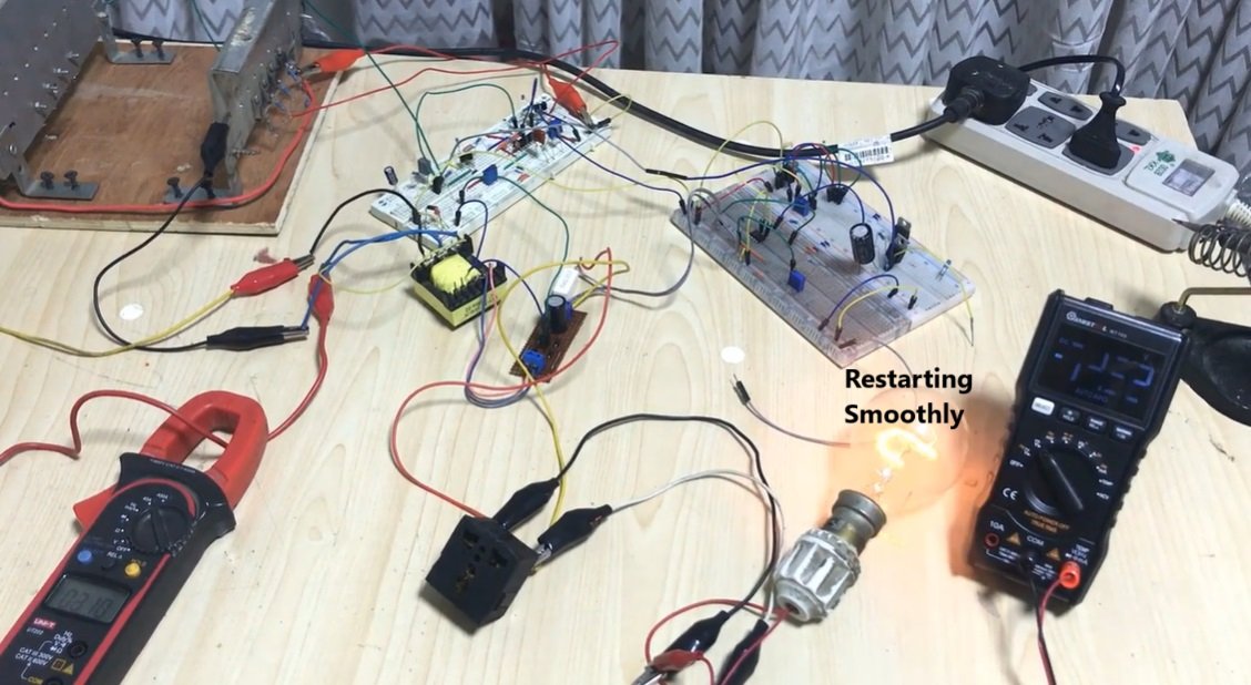
Automatic Recovery:
- Once the overload condition is resolved (e.g., the excessive load is disconnected), the voltage drop across the shunt resistor falls below the reference voltage.
- The op-amp output returns to a low state, deactivating the shutdown signal. The inverter automatically restarts and resumes normal operation without requiring manual intervention.
Key Features and Benefits
-
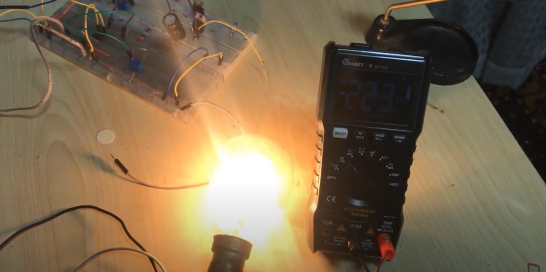
Real-Time Protection:
- The system continuously monitors the output load in real-time, ensuring immediate response to overload conditions.
-
Automatic Recovery:
- The inverter restarts automatically after the overload is removed, providing a seamless user experience.
-
Simple and Reliable Design:
- The use of a shunt resistor and an op-amp makes the circuit simple, cost-effective, and easy to implement while maintaining high reliability.
-
Enhanced Inverter Lifespan:
- By preventing excessive current flow during overload conditions, the system protects critical inverter components, such as transistors and capacitors, from overheating or failure.
Circuit Diagram Overview
-
Key Components:
- Shunt Resistor: High-wattage, low-resistance resistor for current sensing.
- Op-Amp: Configured as a comparator (e.g., LM358).
- Reference Voltage Source: A precise voltage divider circuit or a dedicated voltage reference IC.
- Inverter Controller IC: E.g., SG3525, equipped with a shutdown pin for external control.
-
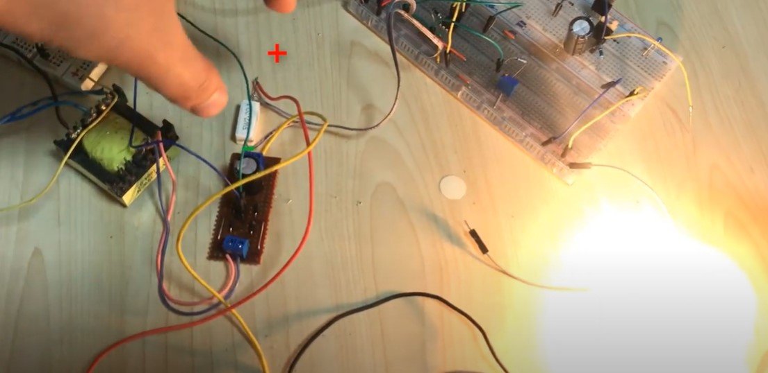
Connections:
- The shunt resistor is placed in series with the load.
- The op-amp compares the shunt voltage with the reference voltage.
- The op-amp output is connected to the shutdown pin of the SG3525 IC.
Applications
- Home Inverters: Ensures safe operation under varying load conditions.
- Industrial Power Systems: Protects inverters used in factories and workshops from equipment overloads.
- Renewable Energy Systems: Enhances reliability and safety in solar or wind power inverters.
Conclusion
The Inverter Overload Protection circuit is a crucial addition to any inverter system, ensuring that the device operates safely under all conditions. By employing a simple yet effective combination of a shunt resistor, op-amp comparator, and inverter control IC, this system offers real-time protection and automatic recovery, extending the inverter's lifespan and improving reliability.
Posted by Ali Aslan at Friday 10th of January 2025 10:40:25 AM