DIY Wireless Charger
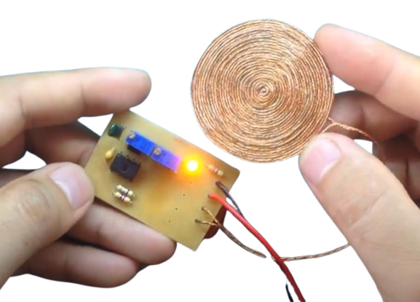
In this project, we design and build a 15W wireless power transmission circuit capable of transmitting power wirelessly over a distance of approximately 1 cm. This system is versatile and can be used for applications such as powering lights inside an aquarium or wirelessly charging devices like older phones.
How It Works
The wireless power transmission system relies on magnetic induction to transfer energy between two coils without physical connections. The system consists of a transmitter circuit and a receiver circuit.
-
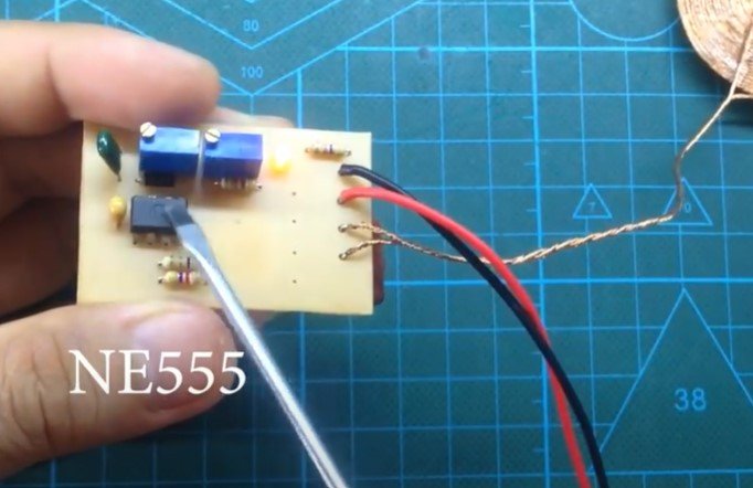
Pulse Width Modulation (PWM) Generation: NE555 Timer IC
- The NE555 timer IC is configured to generate a high-frequency PWM signal. This signal is crucial for driving the MOSFET, which in turn powers the transmitter coil.
- The high-frequency operation ensures efficient energy transfer and minimizes energy losses during transmission.
- The PWM signal's frequency can be fine-tuned to match the resonant frequency of the transmitter and receiver coils for maximum efficiency.
-
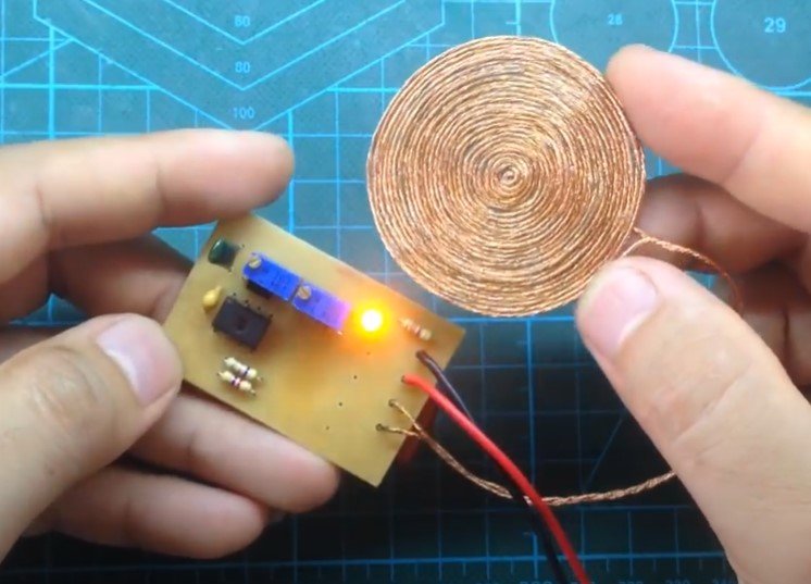
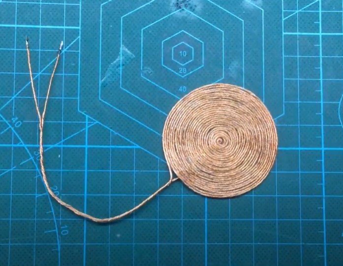
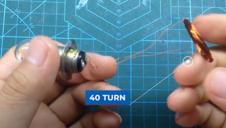
Transmitter Coil
- A custom transmitting coil is constructed using thin wires with 40 turns. Instead of a single large coil, multiple smaller, tightly wound coils are preferred for better energy transfer and efficiency.
- The transmitting coil, when powered by the high-frequency signal, generates an alternating magnetic field. This field is the medium for transferring power wirelessly.

-
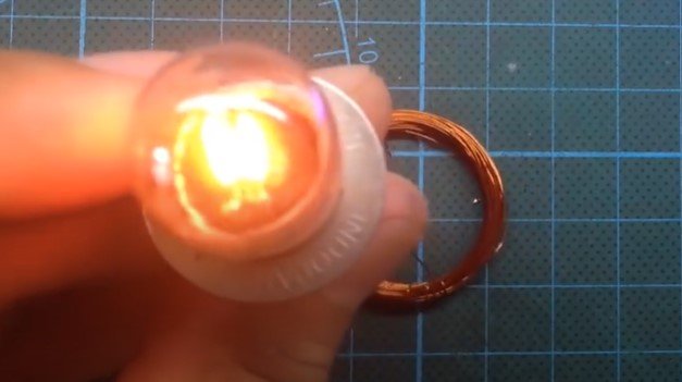
Receiver Coil
- The receiver coil is constructed similarly to the transmitter coil, with the same number of turns and dimensions. It is designed to pick up the alternating magnetic field generated by the transmitter coil.
- When the receiver coil is placed within the magnetic field, it induces an electrical current due to electromagnetic induction.
-
Load Connection
- The output of the receiver coil is connected to the load (e.g., a lamp, phone, or other devices). The induced current powers the load wirelessly.
Building the Circuit
-
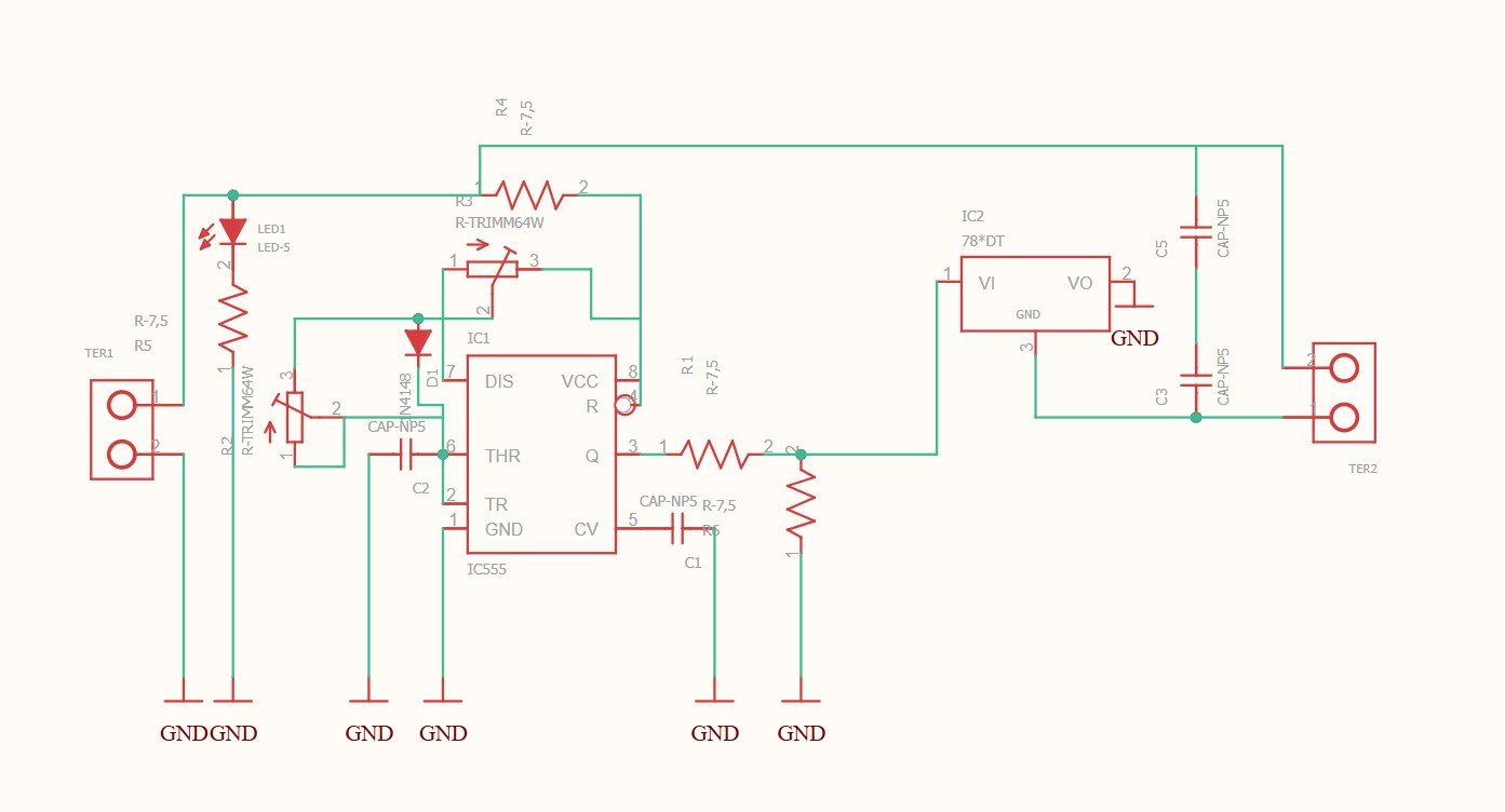
Circuit Design:
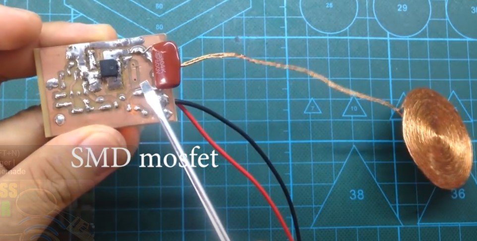
- The transmitter circuit includes the NE555 timer IC configured in astable mode to produce a continuous PWM signal. The output of the NE555 IC is connected to the gate of the MOSFET.
- The MOSFET acts as a switch, rapidly turning on and off to energize the transmitter coil at high frequency.
-
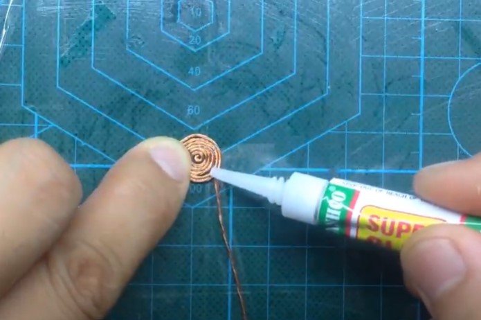
Coil Construction:
- Use enameled copper wire for the coils. Ensure the coils are tightly wound and insulated.
- Both the transmitter and receiver coils should have approximately 30-40 turns, with a diameter and spacing optimized for efficient magnetic coupling.
-
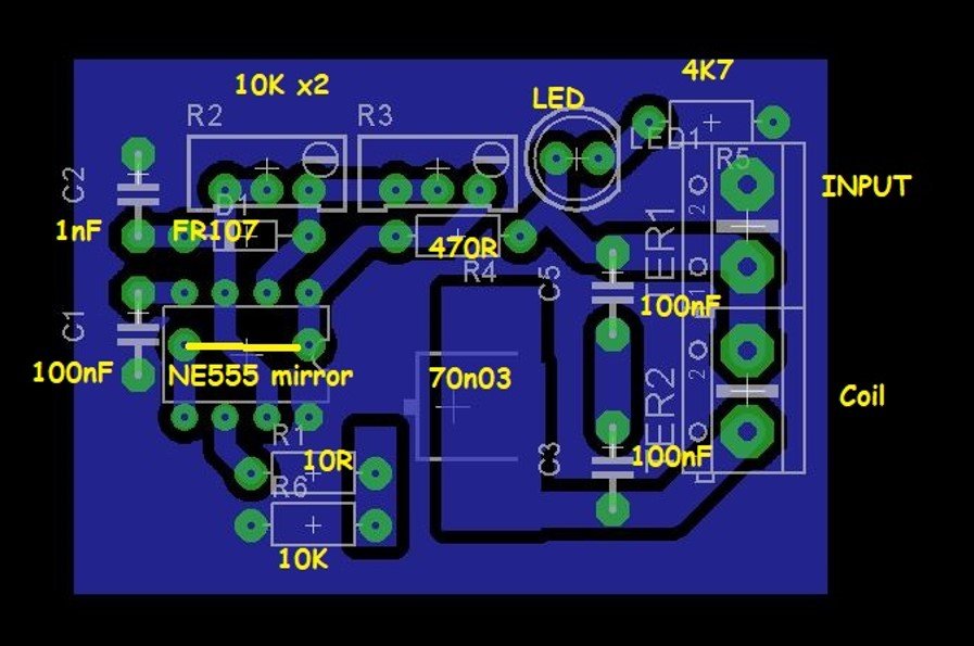
PCB Assembly:
- Create a printed circuit board (PCB) based on the circuit diagram. Place and solder the components, ensuring the connections are secure and the layout minimizes noise.
-
Testing and Tuning:
- Power the transmitter circuit with a DC power source.
- Place the receiver coil near the transmitter coil and connect the load (e.g., a lamp).
- Adjust the PWM frequency using the NE555 configuration to maximize the power transfer.
Applications
-
Aquarium Lighting:
This system can be used to power lights inside an aquarium without the need for wires, ensuring safety and aesthetic appeal. -
Wireless Phone Charging:
By adjusting the receiver circuit to include a rectifier and voltage regulator, the system can charge older phones or other small electronic devices wirelessly. -
Educational and DIY Projects:
This project is an excellent introduction to electromagnetic induction and wireless power transmission, providing practical insights into modern wireless charging technologies.
Advantages of the Design
- No Physical Connections: Eliminates the need for wires, reducing clutter and potential hazards.
- Flexibility: The receiver coil can be customized to suit various loads.
- Ease of Construction: The circuit uses commonly available components like the NE555 IC and MOSFET.
- Scalability: By increasing the coil size and optimizing the circuit, the system can be scaled for higher power and longer transmission distances.
Important Notes
-
Frequency Tuning:
For optimal efficiency, the operating frequency must match the resonant frequency of the coil system. Use a capacitor in parallel with the coils to create a resonant LC circuit. -
Power Source:
A stable DC power supply is essential for consistent performance. -
Heat Dissipation:
High-frequency switching can generate heat in the MOSFET and other components. Use heat sinks or active cooling if necessary. -
Safety Precautions:
Avoid direct contact with the coils during operation as high-frequency currents can cause burns or interference with other electronic devices.
This project is a fun and educational way to explore wireless power transmission. It demonstrates the principles behind modern wireless charging pads and can be a stepping stone for more advanced applications, such as wireless charging stations for electric vehicles.
Posted by Ali Aslan at Saturday 11th of January 2025 06:28:43 PM