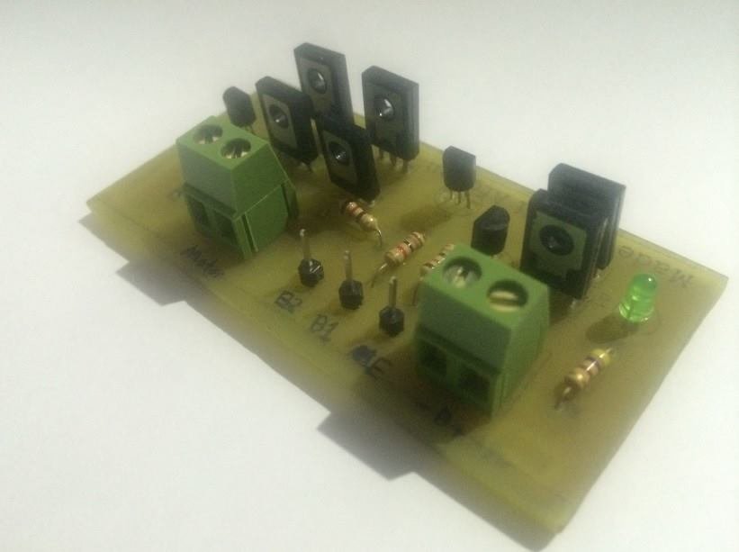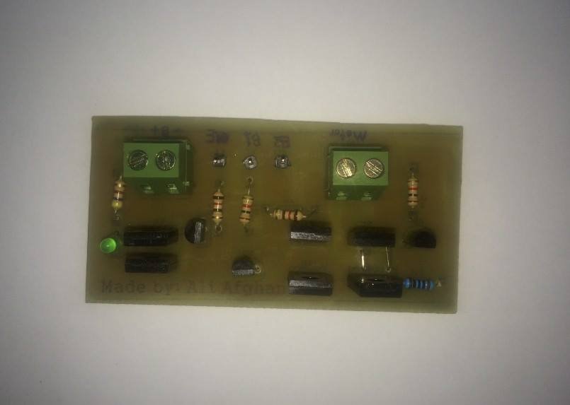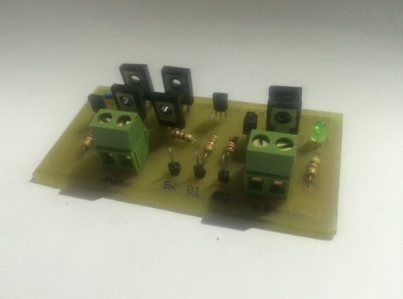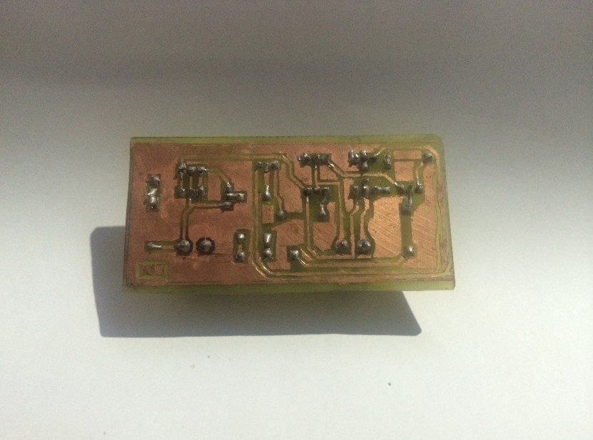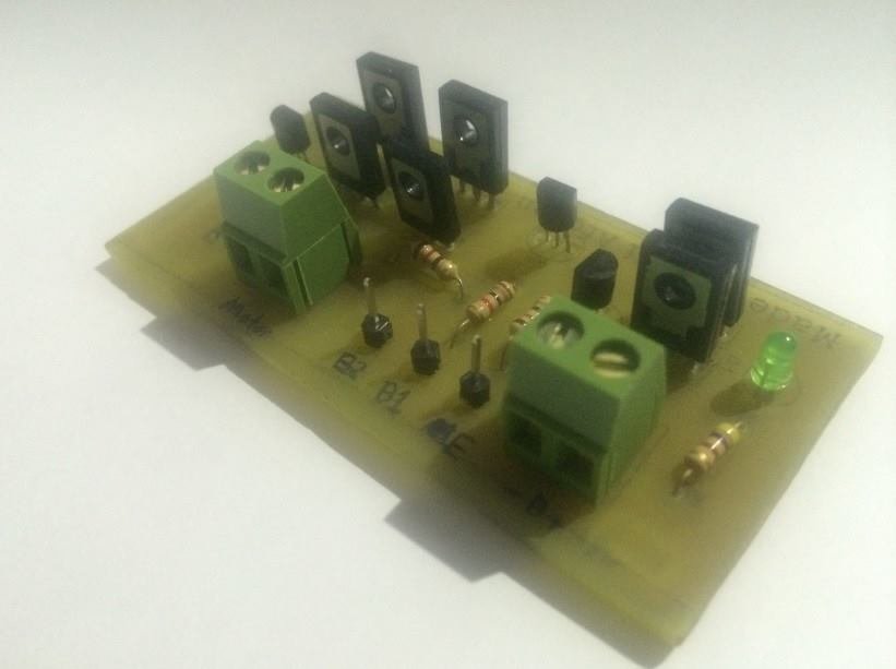
DC Motor PWM H-Bridge Circuit
Understanding the DC Motor PWM H-Bridge Circuit Board
Introduction
The Direct Current (DC) motor Pulse Width Modulation (PWM) H-Bridge circuit board is a fundamental component in the field of robotics and automation. PWM provides a method for controlling the power delivered to an electrical device by manipulating the duration of its 'on' and 'off' states. The H-Bridge circuit, on the other hand, allows for the direction of the current (and hence the motor direction) to be changed. The integration of these two technologies on a single circuit board enables efficient control of a DC motor's speed and direction.
Pulse Width Modulation (PWM)
PWM is a modulation technique used to control the power delivered to electrical devices, such as DC motors. It works by rapidly switching the power supply on and off. The average power delivered to the device is determined by the duty cycle, which is the proportion of the 'on' period to the total period of the cycle. High duty cycles provide more power, thus increasing the speed of a DC motor, while low duty cycles decrease power and thus reduce the speed. This method is highly efficient as the power loss is minimal in switching devices.
H-Bridge Circuit
The H-Bridge circuit derives its name from the typical graphical representation of its four switches, which resemble the letter 'H.' It allows the polarity of the voltage applied to a DC motor to be changed, which in turn changes the motor's direction of rotation. This is achieved by controlling the opening and closing of the four switches in the circuit.
When the switches on one diagonal (say, top left and bottom right) are closed, and the other diagonal is open, current flows in one direction. Conversely, when the switches on the other diagonal (top right and bottom left) are closed, the current flows in the opposite direction, reversing the motor.
DC Motor PWM H-Bridge Circuit Board
When these two technologies are combined on a single circuit board, the result is a powerful tool that can control both the speed and direction of a DC motor. By controlling the duty cycle and the state of the H-Bridge's switches, you can precisely regulate the motor's operation, making this circuit board a versatile tool for a range of applications.
Applications
These circuit boards are widely used in robotics and automation, where precise control of motors is required. They can be found in applications like robotic arms, drones, automatic doors, and even automated guided vehicles (AGVs) in manufacturing plants.
In summary, the DC motor PWM H-Bridge circuit board is a critical technology in the world of electronics and robotics. Its ability to efficiently control both the speed and direction of DC motors makes it an essential tool in various applications.
I'd be happy to provide information on this topic. Here's a detailed discussion on the DC Motor PWM H-Bridge Circuit Board.
Introduction
A DC motor PWM (Pulse Width Modulation) H-bridge circuit board is a sophisticated method of controlling the direction and speed of a DC motor. It utilizes the principles of pulse width modulation (PWM) and H-bridge circuitry.
Pulse Width Modulation (PWM)
Pulse Width Modulation (PWM) is a method used to control the power delivered to electrical devices, especially to inertial loads such as motors. In the case of a DC motor, PWM allows us to adjust the average voltage delivered to the motor and hence, control the speed of the motor without introducing too much electrical noise.
PWM works by rapidly switching the power supply to the motor on and off. When the power is on, the full supply voltage is applied to the motor, but when the power is off, no voltage is applied. By varying the amount of time the power supply is on in relation to the amount of time that the power is off (this is referred to as the duty cycle), the average power and hence voltage supplied to the motor can be varied.
H-Bridge Circuit
An H-bridge is a type of circuit that you can use to get a DC motor to spin both clockwise and counter-clockwise. The H-bridge arrangement is named after the typical graphical representation of such a circuit, which is essentially a square configuration (resembling the letter "H") with the load at the center.
The H-bridge circuit is made up of four switches that can be either transistors or MOSFETs. The switches are controlled in pairs, with each pair controlling the voltage across the motor in one direction. If the switches on the left side are closed and the switches on the right side are opened, the voltage is applied across the motor in one direction. If the switches on the right side are closed and the switches on the left side are opened, the voltage is applied in the opposite direction, reversing the direction of the motor.
PWM H-Bridge Circuit Board
When combined, a PWM H-bridge circuit board can both control the speed of a DC motor (using PWM) and the direction that the motor shaft spins (using an H-bridge).
A microcontroller or other control system can be used to generate the PWM signal, which is then used to control the H-bridge. The control system can adjust the duty cycle of the PWM signal to control the speed of the motor and can control which pairs of switches in the H-bridge are closed to control the direction of the motor.
Applications
PWM H-Bridge circuits are often used in robotics, CNC machines, and other automated systems where precise control of motor speed and direction is required. They can also be used in applications such as electric vehicles, where they can control the speed and direction of the vehicle's drive motor.
Safety Considerations
One important safety consideration when using a PWM H-bridge circuit board is ensuring that both switches of a half-bridge (i.e., the top and bottom switches on the same side of the H-bridge) are never closed at the same time. This would result in a short circuit across the power supply, which could result in significant damage. To prevent this, a phenomenon known as 'shoot-through', control systems often incorporate 'dead time' – a short pause between switching one transistor off and the other on.
In conclusion, a DC Motor PWM H-Bridge Circuit Board is a crucial component in many electronics systems, enabling precise control over the speed and direction of DC motors. Despite its complexity, understanding its working principles can open up a wide array of applications, from robotics and automation to electric vehicles
Components of a DC Motor PWM H-Bridge Circuit Board
Here's a more detailed look at the components that make up a typical DC Motor PWM H-Bridge Circuit Board:
H-Bridge: As discussed earlier, the H-bridge is a circuit that allows a voltage to be applied across a load in either direction. The H-bridge in this context is typically made up of four transistors or MOSFETs. In some cases, integrated circuits (ICs) like the L298N or L293D are used as the H-Bridge.
PWM Generator: The PWM generator can be a microcontroller, an ASIC, or a dedicated PWM generator IC. The PWM generator creates a signal with a specific frequency and duty cycle. The duty cycle of the PWM signal determines the effective voltage across the motor and thus the speed of the motor.
Logic Level Shifter/Driver: This component is often used to interface the PWM generator with the H-Bridge. It ensures that the signals from the PWM generator are at the correct voltage level to effectively switch the transistors/MOSFETs in the H-Bridge.
Power Supply: The power supply provides the necessary voltage and current to the motor. The voltage of the power supply typically determines the maximum speed of the motor, while the current rating of the power supply must be sufficient to meet the motor's demand.
Protection Circuitry: This includes components like flyback diodes which protect the H-Bridge from voltage spikes that can occur when the current to an inductive load like a motor is suddenly interrupted.
Designing a PWM H-Bridge Circuit Board
Designing a PWM H-bridge circuit board involves several steps:
Choosing Components: The components must be chosen to meet the requirements of the motor and the control system. For example, the transistors/MOSFETs in the H-bridge must be able to handle the voltage and current required by the motor.
Circuit Design: The circuit must be designed so that the PWM signal correctly controls the H-bridge and the motor. This involves choosing the correct circuit connections and component values.
PCB Layout: Once the circuit design is complete, the physical layout of the PCB must be designed. This involves placing the components and routing the connections between them.
Testing: After the PCB is manufactured, it must be tested to ensure it works as intended. This typically involves applying a PWM signal and checking that the motor rotates at the correct speed and direction.
Conclusion
In conclusion, a DC Motor PWM H-bridge circuit board is a complex but invaluable tool for controlling DC motors. It is used in a wide range of applications, including robotics, electric vehicles, and automation systems. Designing a PWM H-bridge circuit board requires careful component selection, circuit design, and testing, but the result is a powerful tool for motor control.
Posted by Ali Aslan at Wednesday 10th of May 2023 07:07:48 PM
