Analog Video Transmitter
DIY Analog Video Transmitter: Building a Homemade
In this tutorial, I’ll guide you through creating a simple analog video transmitter to send video signals over radio frequencies. This homemade transmitter will essentially act as a basic "spy camera." The circuit is straightforward, using minimal components, and I’ll explain the basics of analog video signals to help you understand the process.
Since I have an old black-and-white analog TV from my vintage teardown project, we’ll use it to test the signal and display the video. Let’s dive in and see if we can successfully transmit and display video on this retro TV!
Part 1: What Do We Need?
To build this transmitter, you’ll need the following components:
- 1 x analog video camera: LINK eBay
- 1 x 2N2222 NPN transistor: LINK eBay
- 1 x 75R resistor: LINK eBay
- 2 x 10K resistor: LINK eBay
- 1 x 500R Potentiometer: LINK eBay
- 1 x 10pF capacitor: LINK eBay
- 1 x 22pF capacitor: LINK eBay
- 1 x 47pF capacitor: LINK eBay
- 2 x 470pF capacitor: LINK eBay
- 1 x 4.7uF capacitor: LINK eBay
- 1 x 1mH coil: Homemade with 22SWG wire
- 1 x 1N4148 diode: LINK eBay
- 1 x copper wire antenna: LINK eBay
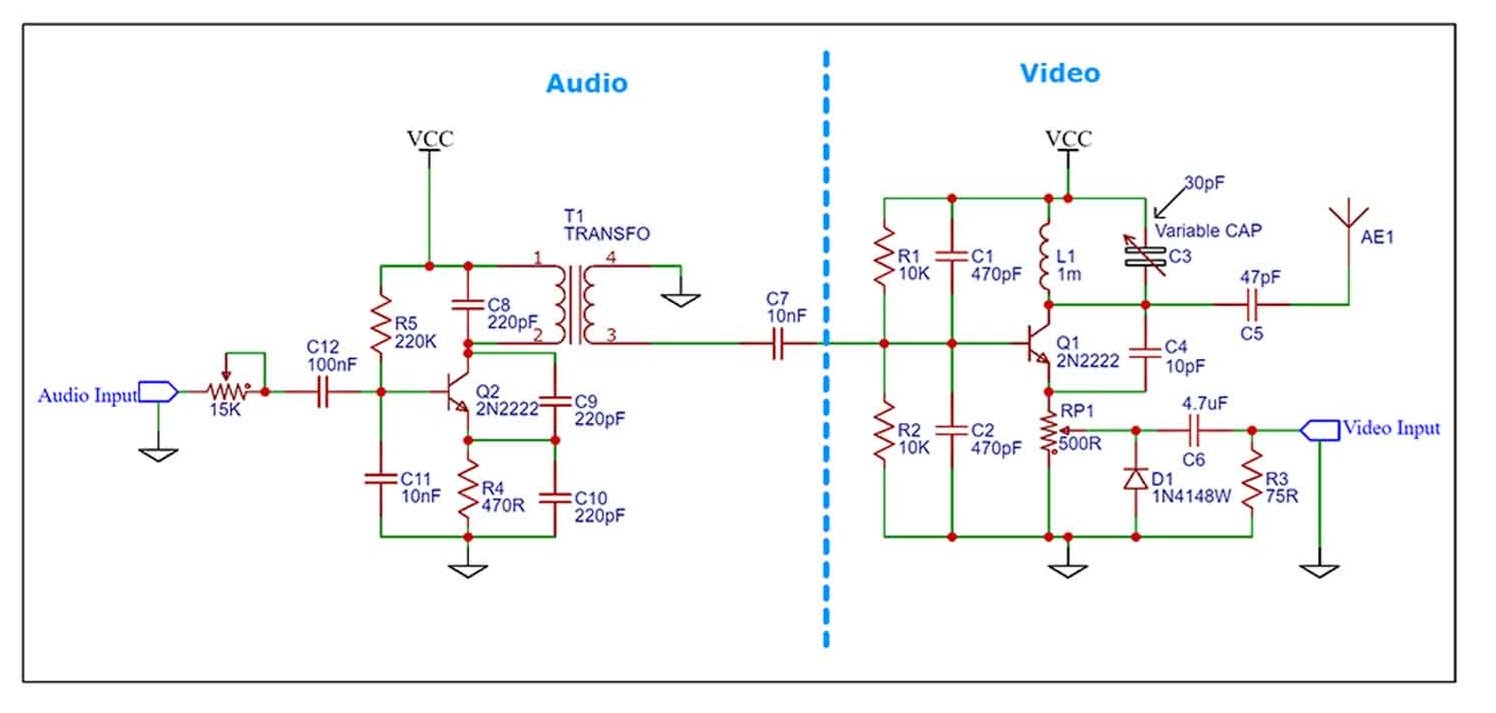
Part 2.1 - Schematic (Audio & Video)
Now we need to send the video signal and for that I will use one of the schematics below which is very common on the internet, just google analog video transmitter and you will get a lot of circuits like this. Since we are only sending video, we can get rid of the audio part but if you also want to send audio, you can use the full schematic.
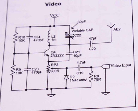
art 2.2 - Schematic (Only Video)
So in case you only want to send video, use the schematic below. From the camera, red wire is VCC, black is ground and the yellow is the video signal. If the camera also has a white cable, that’s means it also has a microphone and audio output. But for my example, I've only used video signal with the schematic below.
Part 3 - Breadboard tests
The coil and the capacitor is creating a so called LC tank. This, as we have seen in so many previous tutorials, will resonate at a specific frequency. That frequency will be our carrier and it must be high frequency since the very high band of the analog TV works between 174MHz and 216 Mhz. Then we take the video signal and we make the convolution with this carrier, so now the high frequency signal will carry our video signal and since we have the antenna connected, this will create an electro-magnetic wave which are basically radio waves and now the TV can read that signal and make the demodulation process and show the pictures on the screen. If you want to know how this analog TV works, watch my previous vintage teardown video.
I first mounted the circuit on the breadboard and instead of a 30pF capacitor I’ve used a variable capacitor. So, in that way I was able to test the circuit for best results and then measured the capacitor and it was 30pF so I’ve used that value for the final circuit.
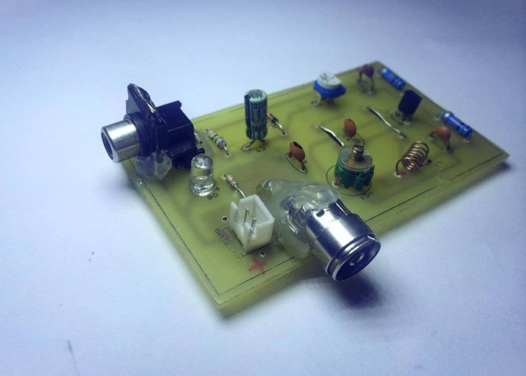
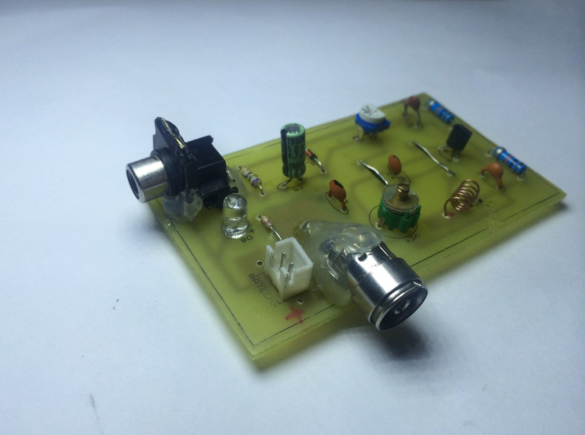
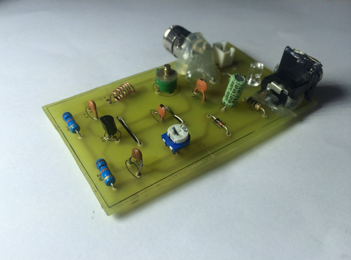
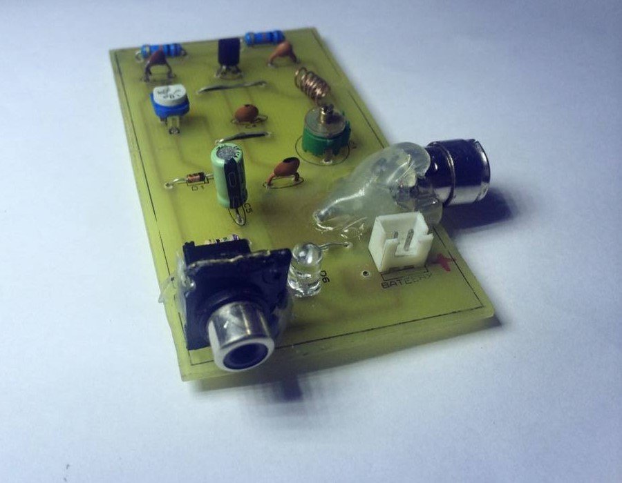
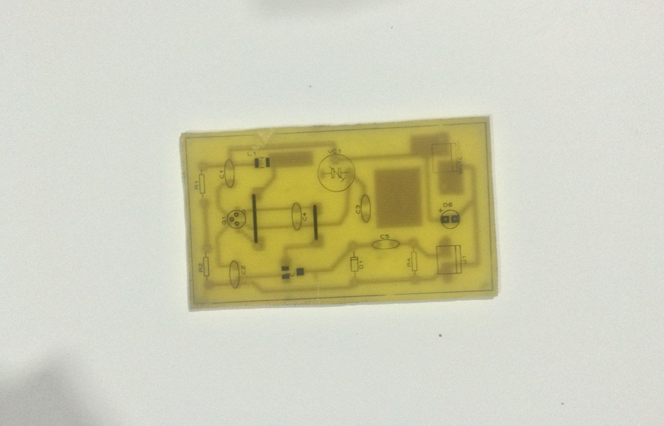
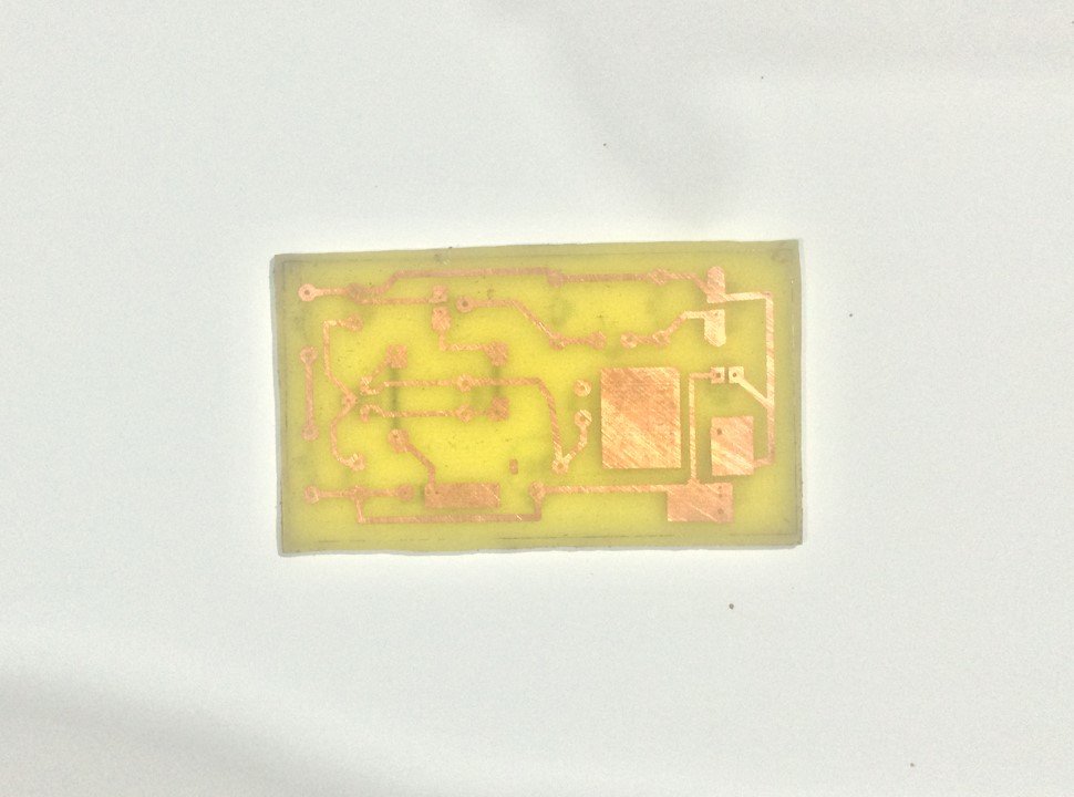
Part 4 - The PCB
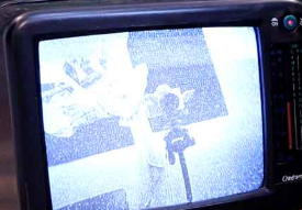
I solder the components. I solder the voltage divider and then the two capacitors. Then I solder the coil with the capacitor for the LC tank and also the BJT transistor and the rest of the components. I have the PCB and I cut it to size and also find a place for the camera as well and solder the wires to VCC and the video input. For the antenna I’ve just used a copper wire. Now we can supply this to a 12V battery and test it out. Start the TV and put it in VHF range of frequencies. I start rotating the knob and after a few seconds of tunning, there we have it. I receive the video from the small transmitter.
Part 5 - Test
The circuit is simple but this technology is still amazing knowing is so old. Now you might need to tune a bit the circuit with the potentiometer or with a variable capacitor. Also, if the frames are moving up and down, usually, the TVs have a synchronizing dial so rotate that till you get steady frames.
Posted by Ali Aslan at Sunday 5th of January 2025 06:37:57 PM